252
8 7 6
5
4 3
2 1
M2007
M2006 M2005 M2004
M2003
M2002 M2001
M2000
M20
M27
M26 M25
M24
M23
M22 M21
M40
M47
M46
M45
M44
M43
M42 M41
M60M67 M66 M65 M64
M63
M62 M61
Y7
Y6
Y5
Y4
Y3
Y2 Y1
Y0
D7007 D7006 D7005 D7004
D7003
D7002 D7001 D7000
D0
D7
D6
D5
D4
D3
D2 D1
D7100D7106D7112
D7117
D7123
D7129
D7135
D7141D7147
D7101D7107D7113
D7118D7124D7130D7136D7142
D7102D7108D7114
D7119D7125D7131D7137D7143
D7103D7109D7115
D7120D7126D7132D7138D7144
D7104D7110
D7121D7127D7133D7139D7145
D7105D7111
D7116D7122D7128D7134D7140D7146
M80M87 M86 M85 M84
M83
M82 M81
M9000
M100
M9002
M9013
C0
MOV H0 D102
MOV K1000 D100
MOV K0 D101
MOV D106 K2M60
WOR K2M20 D104 D104
MOV D104 K2M40
MOV D105 K2Y0
MOV K2M2000 D103
C0
K3600
MOV D107 K2M80
TPID D7000 D0 D100 D7100 K8
MOV H0 EC1D0
MOV H0 EC2D0
FMOV K20 EC1D6 K4
FMOV K20 EC2D6 K4
BMOV EC1D2 D0 K4
BMOV EC2D2 D4 K4
M100
M100
= EC1D18 K106 = EC2D18 K106
M100
TPID Instruction Temperature Control Example II
Below provides an example of an 8 channel PID temperature control. This needs a 32 point VS2 Series Main Unit
and 2 of the VS-4TC-EC expansion cards. Also, a human-machine interface (HMI) is required to proceed for data
setting and status display.
The list of devices used in this example:
Besides the devices on the table above, this instruction will occupy the registers D100~D189. When actually use this
instruction, some unnecessary control items (e.g. Auto/Manual control selection) could be removed from the program
then those items would not occupy components.
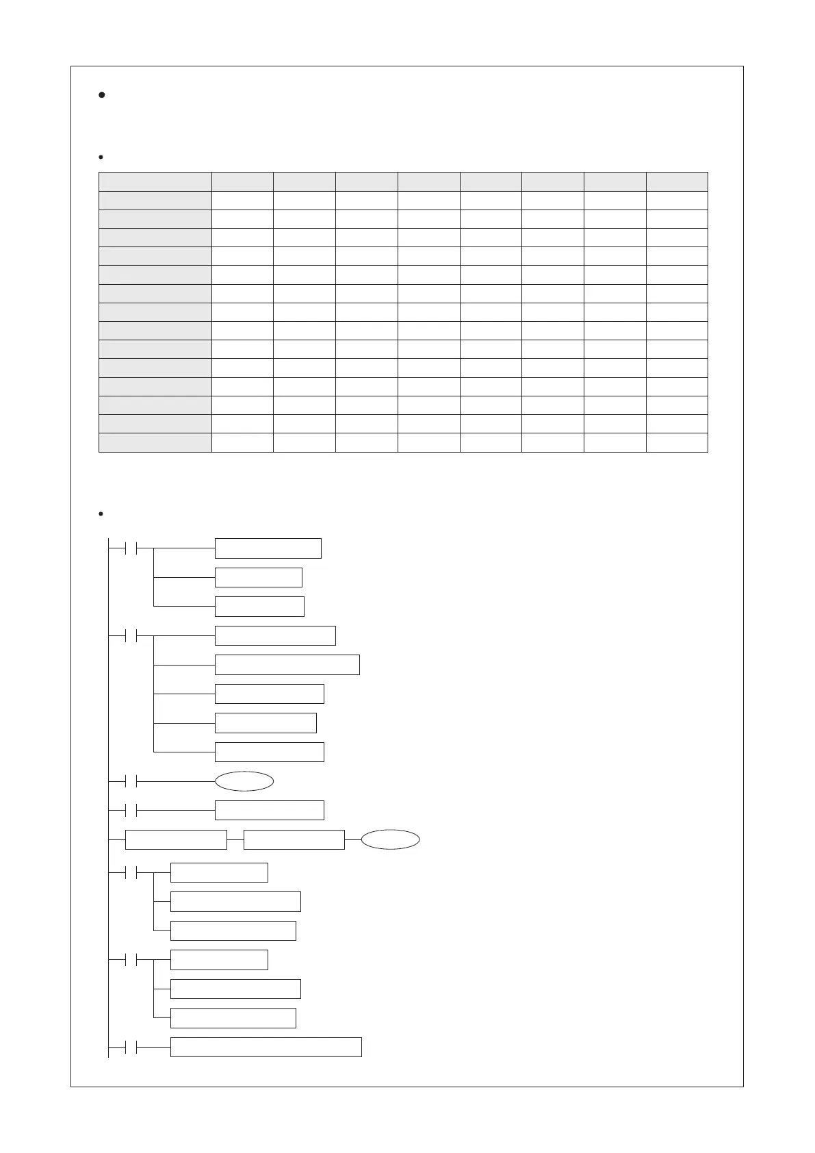
Program example:
Controlled CH #
Auto/Manual Select
AT Command
AT Status
Output Point
Limitation Alarm Status
Deviation Alarm Status
Temp. Set Value (SV)
Temp. Present Value (PV)
Parameter of P Phase (KP)
Parameter of I Phase (TI)
Parameter of D Phase (TD)
Overshoot Repression Value
Limitation Alarm Value
Deviation Alarm Value
Assign the output control cycle = 10 sec. (1000×10 ms. = 10 sec.)
Assign the Responsive Sensitivity level as “Fast” for all the channels.
Assign the control direction of CH1~CH8 as the “Reverse”
operation (Heating).
Setup Auto/Manual control method of CH1~CH8
by Latched M2000~M207.
Use the M20~M27 to trigger the AT function of CH1~CH8.
At this application must use the WOR instruction, the MOV
instruction can't be used here.
Use the M40~M47 to display the AT operational status of the CH1~CH8.
If a coil “ON”, the corresponded channel is processing the AT.
Assign the Y0~Y7 become the control outputs of CH1~CH8, by the output
signals to drive the loaders.
Assign the M60~M67 become the Limitation Alarm indicators for the
overheating warning of CH1~CH8.
Turn the C0 “ON” after one hour to activate the Deviation Alarm monitors, that
would ensure the system is processing under normal temperature.
Assign the M80~M87 become the Deviation Alarm indicators of
CH1~CH8.
Ensure the expansion card in EC1 is a VS-4TC-EC,
and also in the EC2 is a VS-4TC-EC.
Set the external thermocouples at the EC1's VS-4TC-EC to be the K Type.
Set the average temperature values of TC1~TC4 at the EC1's VS-4TC-EC
to be 20 times.
Read the temperature values of the EC1's TC1~TC4 and copy those to the
D0~D3, unit = 0.1 ℃ .
Set the external thermocouples at the EC2's VS-4TC-EC to be the K Type.
Set the average temperature values of TC1~TC4 at the EC2's VS-4TC-EC
to be 20 times.
Read the temperature values of the EC2's TC1~TC4 and copy those to the
D4~D7, unit = 0.1 ℃ .
Operate the TPID instruction.
 Loading...