256
D E C M P P
S1
S2
D
1
2
M
3
○○○○
FNC
110
X Y M S
D.b R.b
KnX KnY
KnM KnS
T C
D,R
V,Z
UnG
K,H
E
" $"
S1
D
S2
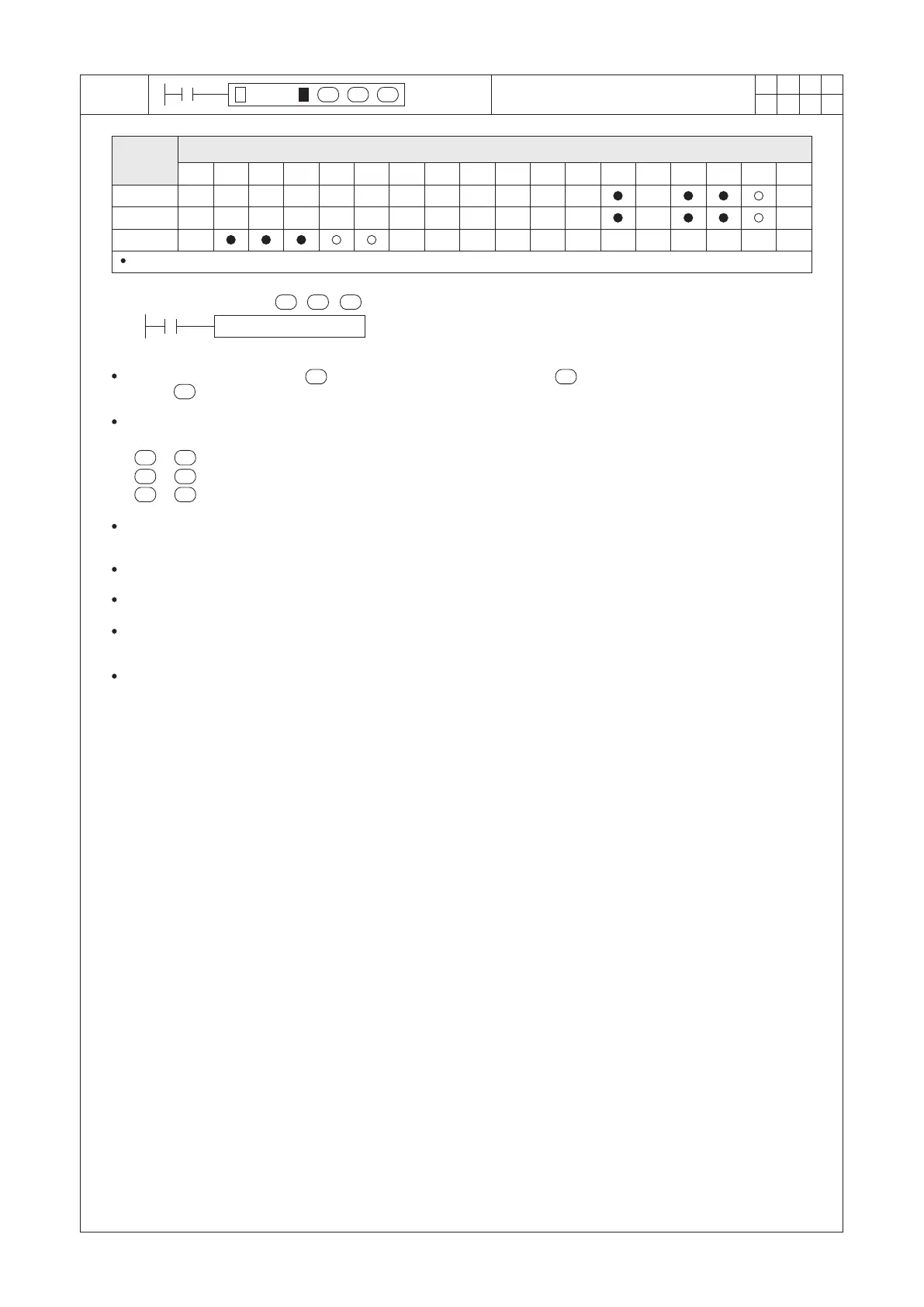
DECMP D0 D10 M0
X0
S1
S2
D
S1
S2
D
Operand
Devices
Compare Two BIN Floating Point
Numbers
D occupies 3 consecutive devices
S1 : the compare value #1
S2 : the compare value #2
D : the compare result; occupying 3 consecutive points
Compare the content value of (compare value #1) with the value of (compare value #2), and save the
result in (compare result).
The DECMP instruction will be enabled when X0 = “ON”, and all the content values are used by the BIN oating
point format.
If > (D1, D0 > D11, D10), then M0 = “ON”;
If = ( D1, D0 = D11, D10), then M1 = “ON”;
If < ( D1, D0 < D11, D10), then M2 = “ON”.
When X 0 = “OFF”, the instruction is disabled, the “ON”/“OFF” status of M0, M1 and M2 remains the same as the
status before X0 = “OFF”.
This instruction is a 32-bit instruction. Therefore, be sure to input DECMP or DECMPP in the program.
Please use serial or parallel links of M0~M2 to generate the result as “≥”, “≤” or “≠”.
If a source operand is assigned to a constant integer K or H, this instruction will automatically convert the number
to BIN oating point number for the calculation. Therefore, could execute the comparison function.
The format for storing a oating point number will occupy two Registers in the PLC system. Please refer to the
section 2-13 “Numerical System” for the reference of the oating point number.
S1 S2
S1 S2
S1 S2