257
D E Z C P P
S1
S2
D
S
1
2
M
3
○○○○
FNC
111
X Y M S
D.b R.b
KnX KnY
KnM KnS
T C
D,R
V,Z
UnG
K,H
E
" $"
S
S1
D
S2
S1 ≦ S2
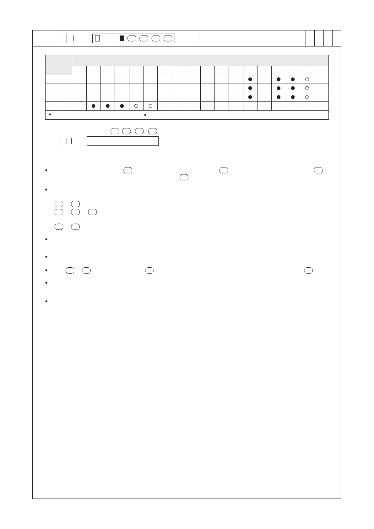
DEZCP D0 D2 D10 M0
X0
S1
S2 S
D
D
Operand
Devices
Compare a BIN Float Number to
BIN Float Zone
S1 S2 S1 S
S S 2
S1 S S2
S1S
S S1 S2
D occupies 3 consecutive devices
S1 : the lower limit of zone compare
S2 : the upper limit of zone compare
S : the compare value
D : the compare result; occupying 3 consecutive points
Compare the content value of (compare value) with the values of (lower limit of zone compare) and
(upper limit of zone compare), then save the result in (compare result).
The DEZCP instruction will be enabled when X0 = “ON”, and all the content values are used by the BIN oating
point format.
If < (D11, D10 < D1, D0, the compare value is less than the lower limit), then M0 = “ON”;
If ≤ ≤ (D1, D0 ≤ D11, D10 ≤ D3, D2, the compare value is between the upper and lower limit), then
M1 = “ON”;
If > (D11, D10 > D3, D2, the compare value is bigger than the upper limit), then M2 = “ON”.
When X0 = “OFF”, the instruction is disabled, the “ON”/“OFF” status of M0, M1 and M2 remains the same as
the status before X0 = “OFF”.
This instruction is a 32-bit instruction. Therefore, be sure to input DEZCP or DEZCPP in the program.
When > , the content value of will become both upper/lower limits to be compared with the .
If a source operand is assigned to a constant integer K or H, this instruction will automatically convert the number
to BIN oating point number for the calculation. Therefore, could execute the comparison function.
The format for storing a oating point number will occupy two Registers in the PLC system. Please refer to the
section 2-13 “Numerical System” for the reference of the oating point number.