264
D E S U B P
S1
S2
D
1
2
M
3
○○○○
FNC
121
X Y M S
D.b R.b
KnX KnY
KnM KnS
T C
D,R
V,Z
UnG
K,H
E
" $"
S1
D
S2
DESUBP D0 D2 D10
X0
2
1.235×10
0
3.2×10
2
1.203×10
S1
S2
D
Operand
Devices
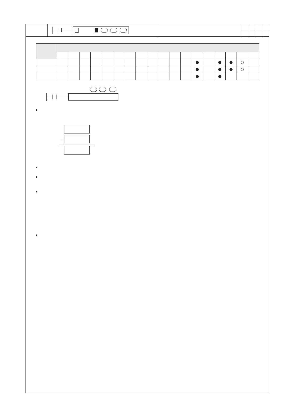
BIN Floating Point Subtraction
(D1, D0) BIN floating number
(D3, D2) BIN floating number
(D11, D10) BIN floating number
When X0 = “OFF” → “ON”, the subtrahend (D3, D2) will be subtracted from the minuend (D1, D0), and the
difference will be stored at the destination device (D11, D10). The components used in the instruction which are
all stored in the BIN oating number format.
S1 : the minuend
S2 : the subtrahend
D : the difference
The format for storing a oating point number will occupy two Registers in the PLC system. Please refer to the
section 2-13 “Numerical System” for the reference of the oating point number.
The result of this instruction will affect the status of the following ags:
When the operated result is equal to “0”, the Addition / Subtraction Zero Flag M9020 turns “ON”.
When the operated result is exceeded the upper limit of the BIN oating point format (positive & negative included),
the Carry Flag M9022 turns “ON”.
When the operated result is less than the insignicant limit of the BIN oating point format (positive & negative
included), the Borrow Flag M9021 turns “ON”.
The available range of the BIN oating point format, please refer to the section 2-13 “Numerical System” for the
reference of the oating point number.
This instruction is a 32-bit instruction. Therefore, be sure to input DESUB or DESUBP in the program.
If a source operand is assigned to a constant integer K or H, this instruction will automatically convert the number
to BIN oating point number for the calculation. Therefore, could execute the subtraction function.


 To Next Page