298
D PH T O S
S
D
1
2
M
3
○○
FNC
164
○
X Y M S
D.b R.b
KnX KnY
KnM KnS
T C
D,R
V,Z
UnG
K,H
E
" $"
S
D
HTOS D0 D10
X0
D
D
S
S
S
X0=ON
11748 (Second)
D10
D
In case of the 32-bit instruction is used, the component is by the format of 32-bit and that occupies 2 registers.
D
S S S
S S S
DHTOSP D0 D10
X0
D
S
145293 (Second)
(D11, D10)
X0=OFF→ON
○
S
D
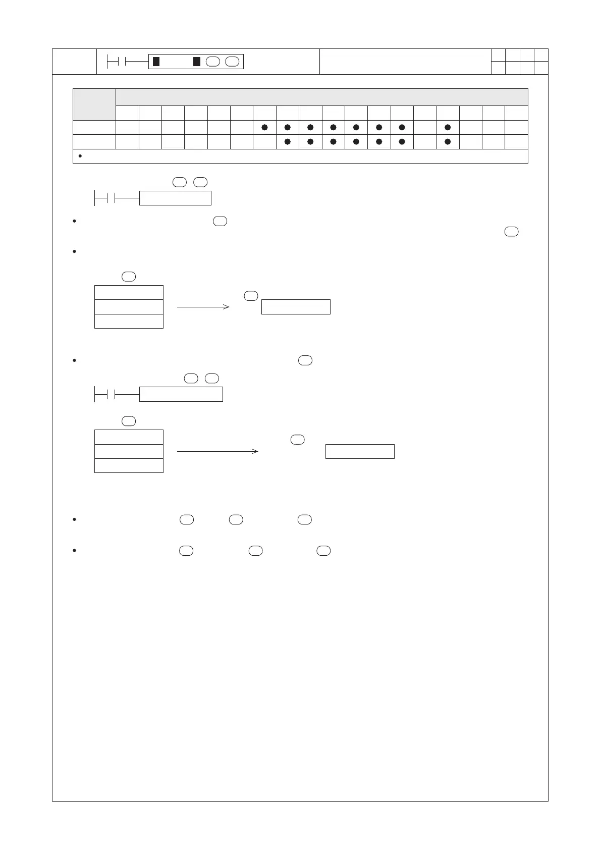
Convert Hour to Second
S occupies 3 components
S : the head register of the time combination to be transferred
D : the transferred result
Operand
Devices
The designated time combination uses three registers to store the Hours, Minutes and Seconds to be
transferred, this instruction converts those into decimal seconds and store the result to the assigned register .
When X0 = “ON”, the instruction will be performed. The time combination at D0~D2 (Hours, Minutes and
Seconds) will convert to equal decimal seconds and the result stores at the D10.
D0 = 03 (Hour)
D1 = 15 (Minute)
D2 = 48 (Second)
D0 = 40 (Hour)
D1 = 21 (Minute)
D2 = 33 (Second)
For the 16-bit instruction, = 0~4, +1 = 0~59, +2 = 0~59. If the content value of the registers
exceeding the range, the PLC will be regarded as an operating error.
For the 32-bit instruction, = 0~32767, +1 = 0~59, +2 = 0~59. If the content value of the registers
exceeding the range, the PLC will regard that as an operational error.
 Loading...