304
D H O U R
D1
D2
S
1
2
M
3
○○
FNC
169
○○
X Y M S
D.b R.b
KnX KnY
KnM KnS
T C
D,R
V,Z
UnG
K,H
E
" $"
S
D1
D2
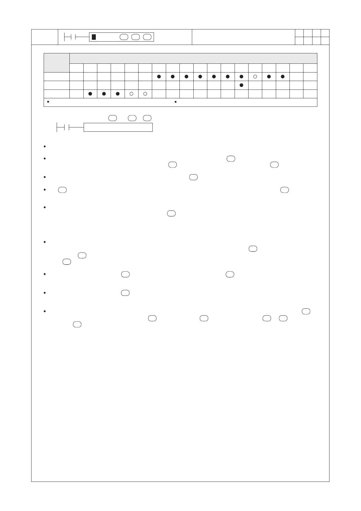
HOUR K1000 D7000 Y0
X0
D1 S D1 S
D1
D2
S
D1
D2S
S
D1D1
D1
D2
D2
D1
D1
D1
Operand
Devices
Hour Meter
For a 16-bit instruction, D1 occupies 2 components For a 32-bit instruction, D1 occupies 3 components
S : the set value of the timer (Unit: hour)
D1 : the present value of the timer (Unit: hour)
D2 : the output contact of the timer
D2
This instruction creates a timer which is using the hour as the counting unit.
When the condition contact is “ON”, this timer increases its present value at . After a while, the present value
of the timer will equal to or larger than the set value , that causes the timer's output contact = “ON”.
The real setting period of the timer = 1 hour × the set value .
The stores the integer number of the present value (in hours). Besides, the register next to the is to store
the remnant present value which is less than 1 hour (in seconds).
As the example diagram above:
When X0 = “ON”, the present value of the register will begin to do the increase counting (hourly). If the
present value of D7000 reaches the set value K1000 (1000 hours), the output contact of the timer Y0 = “ON”.
When X0 = “OFF”, the present value of the timer at the registers will be retained. Therefrom, the characteristic of
this instruction is similar to a retentive timer.
Mostly, this instruction is used to monitor the lifespan of a component or to remind the regular maintenance.
For to retain the present value of the timer during the power cut off, please assign the to a latched register.
If assign the to an unlatched general register, when the power cut off or the PLC is “STOP”, the content value
of the will be reset to “0”.
After the timer's output contact = “ON”, the timer's present value at the will continuously execute the
increase counting.
When the timer's present value reaches the maximum value of a 16-bit or 32-bit register, the counting will be
stopped.
Even though, the driving condition contact of this instruction (X0 in this example) is “OFF”, its output contact
will turn “ON” as long as the present value >= the set value ; on the other hand, if < , that will
cause the = “OFF”.
D1
D1