318
D B K P
S1
S2
n
D
1
2
M
3
○
FNC
192
X Y M S
D.b R.b
KnX KnY
KnM KnS
T C
D,R
V,Z
UnG
K,H
E
" $"
S1
D
S2
n
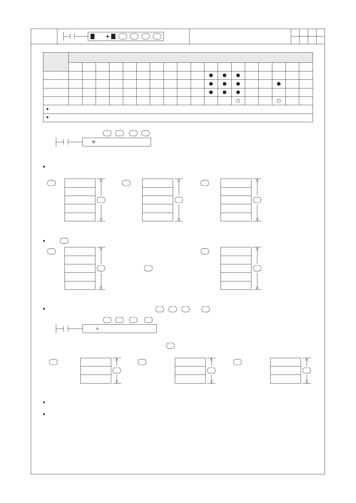
S1 : the head ID of the summand block
S2 : the addend or the head ID of the addend block
D : the head ID of the sum block
n : the length of the data block to be calculated
X0
D
S1 S 2
BK P D0 D10 D20 K5
n
D0
D1
D2
D3
D4
K100
K200
K234
K400
K–1
S1
D10
D11
D12
D13
D14
K10
K50
K–10
K150
K8
n n
=
+
S2
D20
D21
D22
D23
D24
K110
K250
K224
K550
K7
n
D
D0
D1
D2
D3
D4
K100
K200
K234
K400
K–1
S1
n
=
+
D20
D21
D22
D23
D24
K200
K300
K334
K500
K99
n
D
S2
K100
X0
D
S1 S 2
DBK D0 D10 D20 D100
n
(D5, D4)
(D1, D0)
S1
n
=
+
(D3, D2)
(D15, D14)
n
(D13, D12)
(D11, D10)
S2
(D25, D24)
n
(D23, D22)
(D21, D20)
D
K123456
K200000
K5
K–2
K123456
K100
K199998
K246912
K105
For a 16-bit instruction, S1, S2 and D occupies n components individually (except that S2 is using K or H)
For a 32-bit instruction, S1, S2 and D occupies (2×n) components individually (except that S2 is using K or H)
When X0 = “OFF” → “ON”, each component in the summand block (D0~D4) will be added to the corresponding
component at the addend block (D10~D14), and store the result into the sum block (D20~D24) one by one.
For a 32-bit instruction, the components at the , , and are all organized by the 32-bit format.
D
S1 S2
n
Assume the content value of the 32-bit instruction's at (D101, D100) is equal to K3, the treatment is as the
following:
The calculation may have the “Borrow” or “Carry” action, but that will not affect the corresponding flag.
The components which used by the instruction could not be overlapped. Otherwise, the PLC will regard that as an
operational error.
If the is appointed by a constant number (e.g. K100), the execution method is shown below.
S2
Operand
Devices
Block Data Addition
n
 Loading...