350
D B N D A
I
P
D
S
FNC
261
1
2
M
3
○
X Y M S
D.b R.b
KnX KnY
KnM KnS
T C
D,R
V,Z
UnG
K,H
E
" $"
S
D
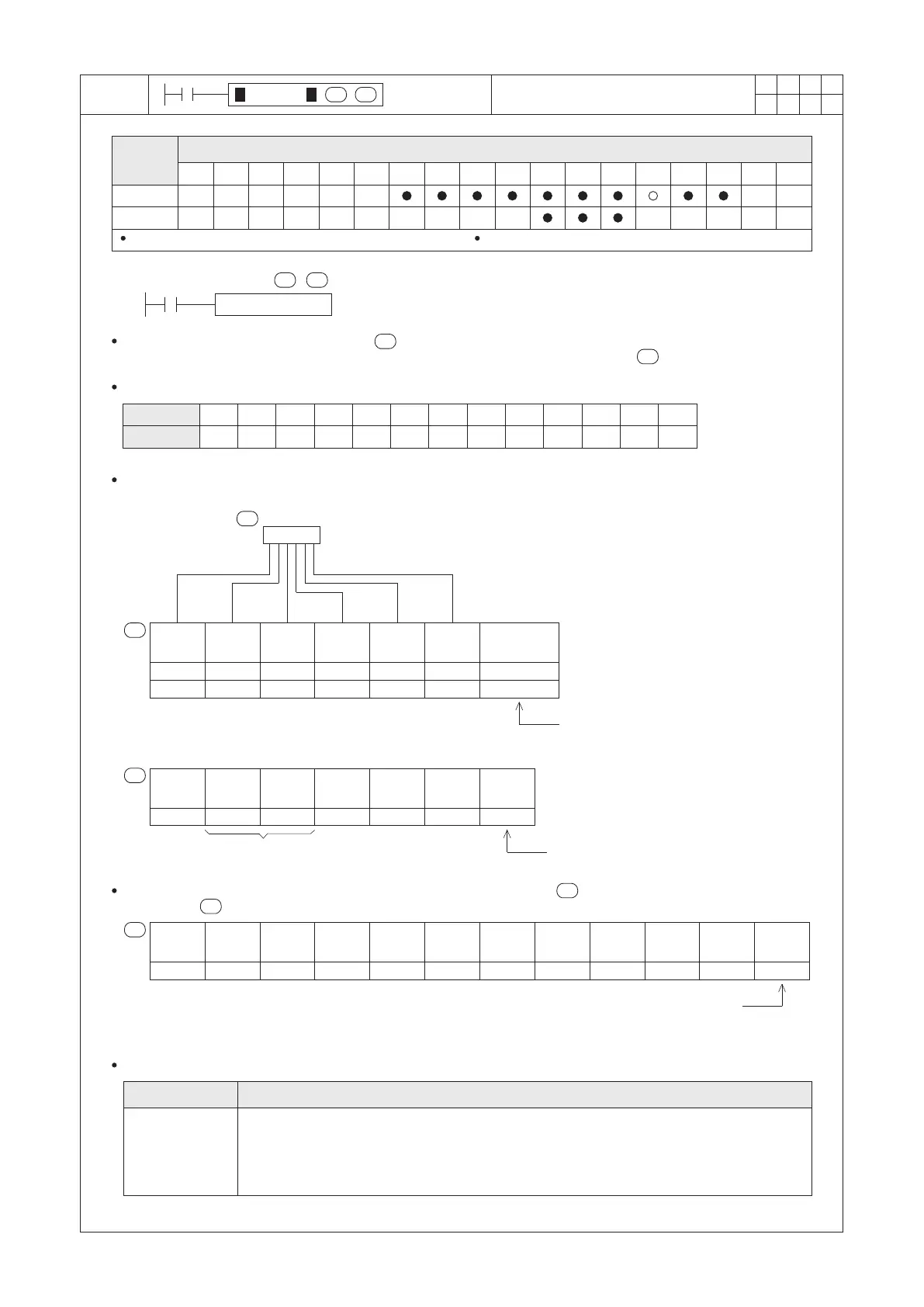
S : the source BIN number to be converted
D : the head ID of the converted decimal ASCII string
BINDA D10 D0
X0
This instruction uses a BIN number at the to perform the conversion and the result is using a decimal format
ASCII string to explain the number, then stores the string into the devices started from .
S
S
When the X0 = “ON”, this 16-bit instruction converts the content of a BIN number in the D10, then stores the result
using an ASCII code string to D0~D3.
30H 31H 32H 33H 34H 35H 36H 37H 20H
2DH
38H 39H
D
D
00H
0
1
2
3
4
5
6
7
SPACE
–
8
9
NULL
If the D10 is positive, the sign code will fill in 20H;
else the D10 is negative, the sign code will fill in 2DH.
Assume the content value at the D10 is 125, the result is below:
For a 32-bit instruction, the structure of the result string starting from the is shown below.
(assume the = D0)
9
10
8
10
7
10
6
10
5
10
4
10
3
10
2
10
1
10
For a 32-bit instruction, the available range is
–2,147,483,648 ~ +2,147,483,647.
Therefore, with a sign code, that will occupy 11 bytes.
S
D3
2DH( –) 31H(1) 32H(2) 35H(5)
4
10
3
10
2
10
1
10
0
10
38H( 8) 39H(9)
0H or retain
–12589
D10
End of string
D
If the M9091 = “OFF”, will ll in 0000H.
If the M9091 = “ON”, will retain the
original data at D3.
D3
20H( )
20H( ) 31H( 1) 32H(2) 35H(5) 0H
D
20H( )
It is
positive.
Empty, ll in 20H.
1
2
5
Assume the M9091 = “OFF”.
D
D
D
0H or 20H
0
10
If the M9091 = “OFF”, will ll in 00H.
If the M9091 = “ON”, will ll in 20H.
The related special device for this instruction:
M9091
Operand
Devices
Convert BIN Number to Decimal
ASCII String
For a 16-bit instruction, D occupies 4 components For a 32-bit instruction, D occupies 6 components
Sign & Number
ASCII Cord
This instruction will use the following ASCII conversion table:
D0
Lower
8 bits
D0
Upper
8 bits
D1
Lower
8 bits
D1
Upper
8 bits
D2
Lower
8 bits
D2
Upper
8 bits
Sign code
D0
Lower
8 bits
D0
Upper
8 bits
D1
Lower
8 bits
D1
Upper
8 bits
D2
Lower
8 bits
D2
Upper
8 bits
D0
Lower
8 bits
D0
Upper
8 bits
D1
Lower
8 bits
D1
Upper
8 bits
D2
Lower
8 bits
D2
Upper
8 bits
D3
Lower
8 bits
D4
Lower
8 bits
D5
Lower
8 bits
D3
Upper
8 bits
D4
Upper
8 bits
D5
Upper
8 bits
Sign code
Assign the BINDA operating mode.
16-bit instruction: When M9091= “OFF”, will add the end of string 0000H after the result.
When M9091=“ON”, will only convert the data without to add the end of string.
32-bit instruction: When M9091=“OFF”, will add the end of string 00H at the result's last upper 8 bits.
When M9091=“ON”, will add the end of string 20H at the result's last upper 8 bits.
Description
Relay ID No.
 Loading...