372
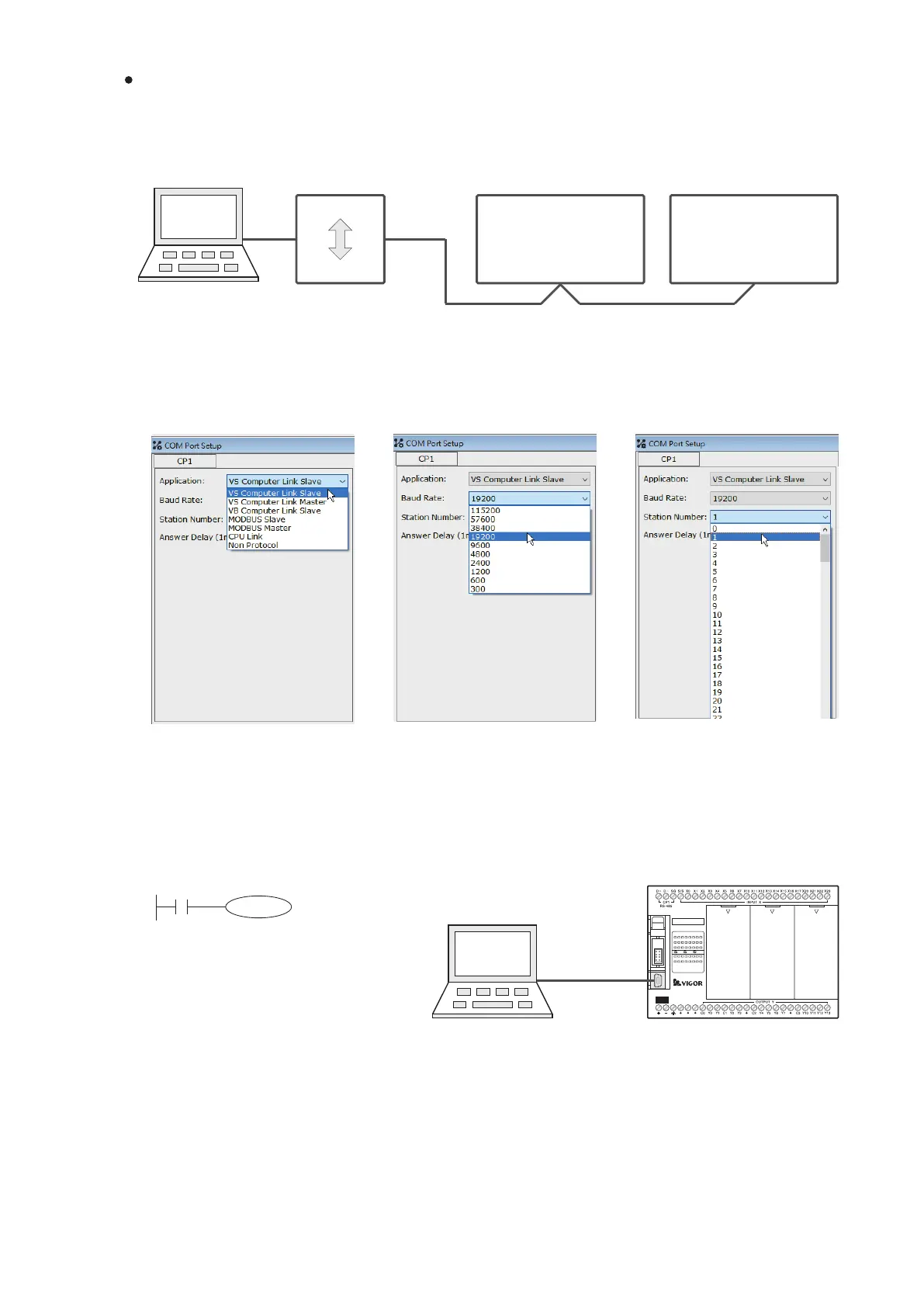
① Edit the project of PLC Station #1
Converter
USB
RS-485
RS-485
VS Computer Link Slave
Baud Rate: 19200 bps
Station No.: #1
VS PLC Station #1
CP1
VS Computer Link Slave
Baud Rate: 19200 bps
Station No.: #2
VS PLC Station #2
CP1
USB
Ladder Master S
Please follow the procedures below to operate the test:
※ Usually the default delay response time is not necessary to change, except that:
When the communication mistake is caused by the signal collision in the circuit, try to extend the delay response
time.
C0
K1000
M9013
VS1-32M R
X0 1 2
3 4
5
6 7
10
21 22
23
RUN
ERR
Y0 1 2
3 4
5
6 7
10
11 12
13
PWR
20
11 12
13
14
15 16
17
DC2 4V
INP UT
STOP
MC
RUN
VSPC-200A
USB
Ladder Master S
Application Example
In this example, a computer uses its USB port to connect with an USB to RS-485 converter to transfer the
communication signal to the RS-485 interface. Then, the RS-485 is connected to two VS series PLC’s CP1 those
station numbers are assigned to #1 and #2. After that, executes the Ladder Master S programming software on the
computer to connect with the station #1 and station #2 PLCs for to read the project, control STOP/RUN and
monitor those PLCs.
Use the Ladder Master S to set the CP1's parameters of PLC Station #1 and compile relevant program. Then,
connect to the USB programming port of Station #1 and write the project into the PLC Station #1.
Set the application type:
VS Computer Link Slave
Set the baud rate:
19200 bps
Set the station No.:
Station #1
The program writes to the PLC
Station #1.
By the USB programming port, the project is written into the PLC
Station #1
PLC Station #1