373
② Edit the project of PLC Station #2
③ After complete to edit and load the projects to those two PLCs sequentially, do the wiring jobs between the
computer, RS-485 converter and two PLCs’ CP1.
④ Usually the application of the SCADA software is to monitor equipments through the communication network. In
this example, the Ladder Master S replaces the SCADA software to execute the monitoring work. However, the
Ladder Master S can only be connected to a single PLC at a time. Therefore, it is necessary to link and test with
different PLC stations one by one.
In the real applications, when a communication system is nished the wiring but which cannot function normally,
may use the Ladder Master S to test each station one by one to ensure the correctness of communication network.
Set the station No.:
Station #2
The program writes to the PLC Station #2.
C100
K2000
M9013
By the USB programming port, the project is written into the PLC
Station #2
PLC Station #2
VS1-32M R
X0 1 2
3 4
5
6 7
10
21 22
23
RUN
ERR
Y0 1 2
3 4
5
6 7
10
11 12
13
PWR
20
11 12
13
14
15 16
17
DC2 4V
INP UT
STOP
MC
RUN
VSPC-200A
USB
Ladder Master S
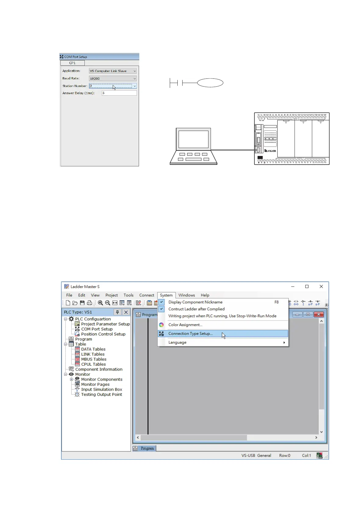
Use the Ladder Master S to set the CP1's parameters of PLC Station #2 and compile relevant program. Then,
connect to the USB programming port of Station #2 and write the project into the PLC Station #2.
To set the connection method of the Ladder Master S: