379
VS1-32M R
X0 1 2
3 4
5
6 7
10
21 22
23
RUN
ERR
Y0 1 2
3 4
5
6 7
10
11 12
13
PWR
20
11 12
13
14
15 16
17
DC2 4V
INP UT
STOP
MC
RUN
VSPC-200A
USB
Ladder Master S
③ Edit the project of the Master PLC
M9000
MOV D0 K2Y0
ADD D0 K100 D1
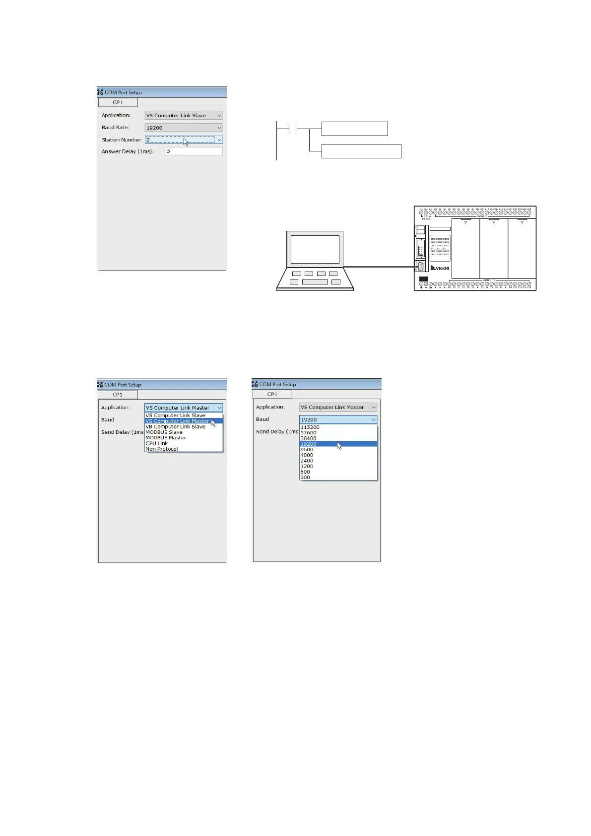
② Edit the project of Slave PLC #2
The program writes to the Slave PLC #2
By the USB programming port, the project is written into the Slave
PLC #2
Use the Ladder Master S to set the CP1's parameters of Slave PLC #2 and compile relevant program. Then,
connect to the USB programming port of Slave #2 and write the project into the PLC.
Set the station No.:
Station #2
Slave PLC #2
Send the content value of D0 to the
output points Y0~Y7.
Add 100 to the content value of D0
and store it to the D1.
Use the Ladder Master S to set the CP1's parameters of Master PLC. Compile the LINK communication table, the
LINK instruction and relevant program. Then, connect to the USB programming port of Master and write the
project into the PLC.
Set the application type:
VS Computer Link Master
Set the baud rate:
19200 bps
※ Usually the default delay response time is not necessary to change, except that:
When the communication mistake is caused by the signal collision in the circuit, try to extend the delay response
time.