390
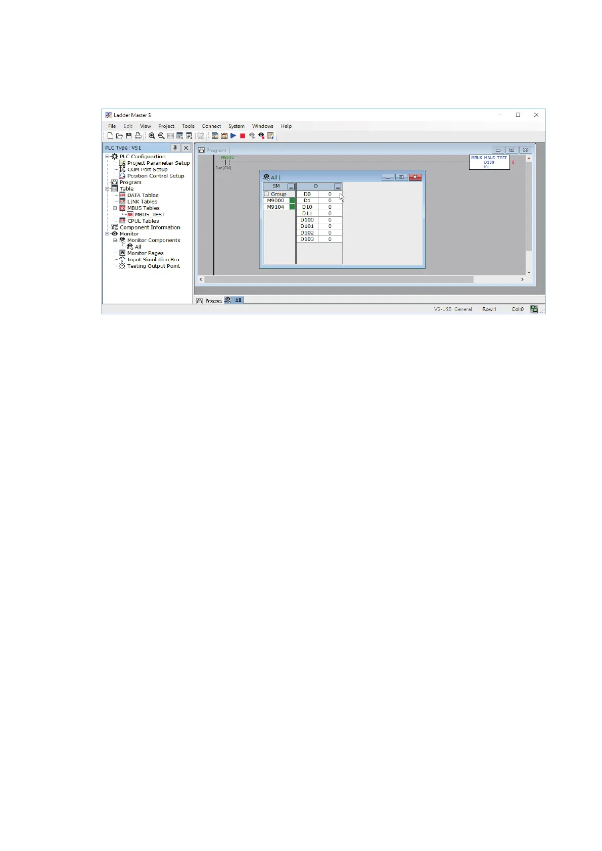
⑤ Read the project from the Master PLC then execute the monitor mode, at the screen to add and monitor the
components D0, D1, D10 and D11.
④ After sequentially edit and load the projects to those PLCs, do the wiring jobs between three PLCs. Then, connect
the computer to the USB programming port of the Master PLC, to test and monitor the process through the
Ladder Master S.
When the example is performing, the data at every PLC will follow its own program and the communication table to
execute the operation below.
1. The content value of Master's D0 is written into the 40000 at the Slave PLC #1 via communication (the rst
command in the communication table that 40000 is corresponding to the D0).
At the Slave #1, the content value of D0 is sent to its output points Y0~Y7. Therefore, when the value of
Master’s D0 is 1, the Y0 at the Slave #1 turns “ON”; when the value of Master's D0 is 5, the Y0 and Y2 at the
Slave #1 turn “ON”, and so forth.
At the PLC Slave #1, its content value of D0 will be added 100 up and stored to the D1.
Afterward, the PLC Master reads the value of 40001 at the Slave #1 via the communication and stores the value
to the Master's D10 (the second command in the communication table that 40001 is corresponding to the D1).
Thus, to observe the value of D10 at the Master that is always equal to the content value of D0 added up to 100
if the communication is successful.
2. The content value of Master’s D1 is written into the 40000 at the Slave PLC #2 via communication (the third
command in the communication table that 40000 is corresponding to the D0). At the Slave #2, the content
value of D0 is sent to its output points Y0~Y7. Therefore, when the value of Master's D1 is 1, the Y0 at the Slave
#2 turns “ON”; when the value of Master's D1 is 7, the Y0, Y1 and Y2 at the Slave #1 turn “ON”, and so forth.
At the PLC Slave #2, its content value of D0 will be added 100 up and stored to the D1.
Afterward, the PLC Master reads the value of D1 at the Slave #1 via the communication and stores the value to
the Master's D11 (the fourth command in the communication table that 40001 is corresponding to the D1).
Thus, to observe the value of D11 at the Master that is always equal to the content value of D1 added up to 100
if the communication is successful.
By the MODBUS communication, the MBUS instruction and its table at the Master PLC that produces the following
results:
1. The content value of the Master's D0 is output to the points Y0~Y7 of the Slave #1.
2. The content value of the Master's D10 equals to the sum of the content value of its D0 and 100.
3. The content value of the Master's D1 is output to the points Y0~Y7 of the Slave #2.
4. The content value of the Master's D11 equals to the sum of the content value of its D1 and 100.