405
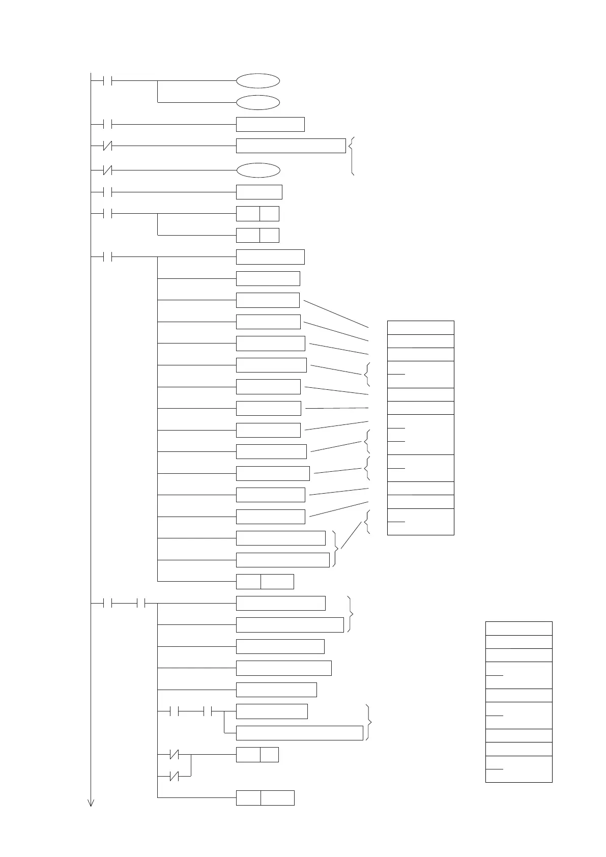
Edit the program for the left PLC (Master).
M9002
T200
M0
M1
M0
M4
M4
M7
M9002
T200
M9000
T200
MOV K1 D100
ALTP M0
PLS
MOV K12 D50
CCD D53 D104 K6
WAND D104 HFF D104
HEX D61 D106 K2
CMP D104 D106 M3
CMP D56 K0 M6
MOV K16 D0
MOV H10 D1
MOV H02 D2
PLF
RS D1 D0 D51 D50 K1
M1
M2
K10
M9100
SET
M9161
M9168
M7
SET
Y0
Activate the sending out flag of the CP1
M9101
Calculate the SUM Check
code from the received
data string, take the last
two digits then store that
into D104.
Convert the received SUM Check code
into HEX code and store to D106.
Compare the calculated with the
received SUM Check codes, see
whether they are equal
Check whether the error code is “0”
(no error).
If the SUM Check codes are not equal or the error
code is not “0”, turn the Y0 “ON” that means the
reading communication is unsuccessful.
MOV D100 D3
DMOV H07 D4
MOV H20 D6
MOV HA0 D7
MOV H01 D8
DMOV H00 D9
DMOV H01 D11
MOV H10 D13
MOV H03 D14
ASCI D102 D15 K2
CCD D3 D102 K10
RST
M9101
MOV D57 D111
SMOV D58 K2 K2 D111 K4
D11
D12
D13
D14
D1
D2
D3
D4
D5
D6
D7
D8
D10
D9
L
H
L
H
L
H
L
H
10H
02H
20H
01H
10H
03H
07H
00H
A0H
01H
00H
00H
01H
00H
43H
41H
〜
D L E
STX
DLE
ETX
D15
D16
Clear the recive completed flag
L
H
L
H
L
H
10H
06H
01H
10H
03H
03H
00H
00H
00H
00H
30H
34H
D L E
Error code
ACK
Content
value of
D1
DLE
ETX
The Slave’s feedback
data string
D51
D52
D53
D54
D55
D56
D57
D58
D59
D60
D61
D62
The command data
string from the Master
Assign the RS, CCD... instructions to operate in the 8-bit mode
Assign the SMOV instruction to operate in the HEX mode
D100 stores the Slave's station No. to be communicated, in
this example it is 1.
D0 is the number of data to transmit,
D1 is the transmit buffer space.
D50 is the number of data to receive,
D51 is the receive buffer space.
Comm.
procedures
switching timer
Take turns to execute the reading or writing procedure
M1 is the pulse for to send out the communication command of
reading procedure
M2 is the pulse for to send out the communication command of
writing procedure
Set the number of data bytes to be received
Set the number of data bytes to be sent
This program block is to
constitute the data
reading command of
the “VS Protocol”.
In this example, it reads
the register D0 at the
Slave station #1.
Recive
completed
ag
If the SUM Check codes
are equal and no error
code, the communication
is successful. Convert the
received value and store
that into D111.
Station No.
SUM
Check
Number
of data
Bytes
Station No.
Number
of data
Bytes
Function
code
Head
number
of devices
Number
of
devices
SUM
Check
Device code
Continue on next page