432
1
2
M
3
○
FNC
301
X Y M S
D.b R.b
KnX KnY
KnM KnS
T C
D,R
V,Z
UnG
K,H
E
" $"
S1
S2
○
D1
D2
D J O G F
S1
S2
D1 D 2
JOGF K300 D20 Y0 Y4
M0
S1 S2
D1 D2
S2
S1
D1
D2
1
2
M
3
○
FNC
302
○
D J O G R
S1
S2
D1 D 2
S1
S1
S1
S1 S 1
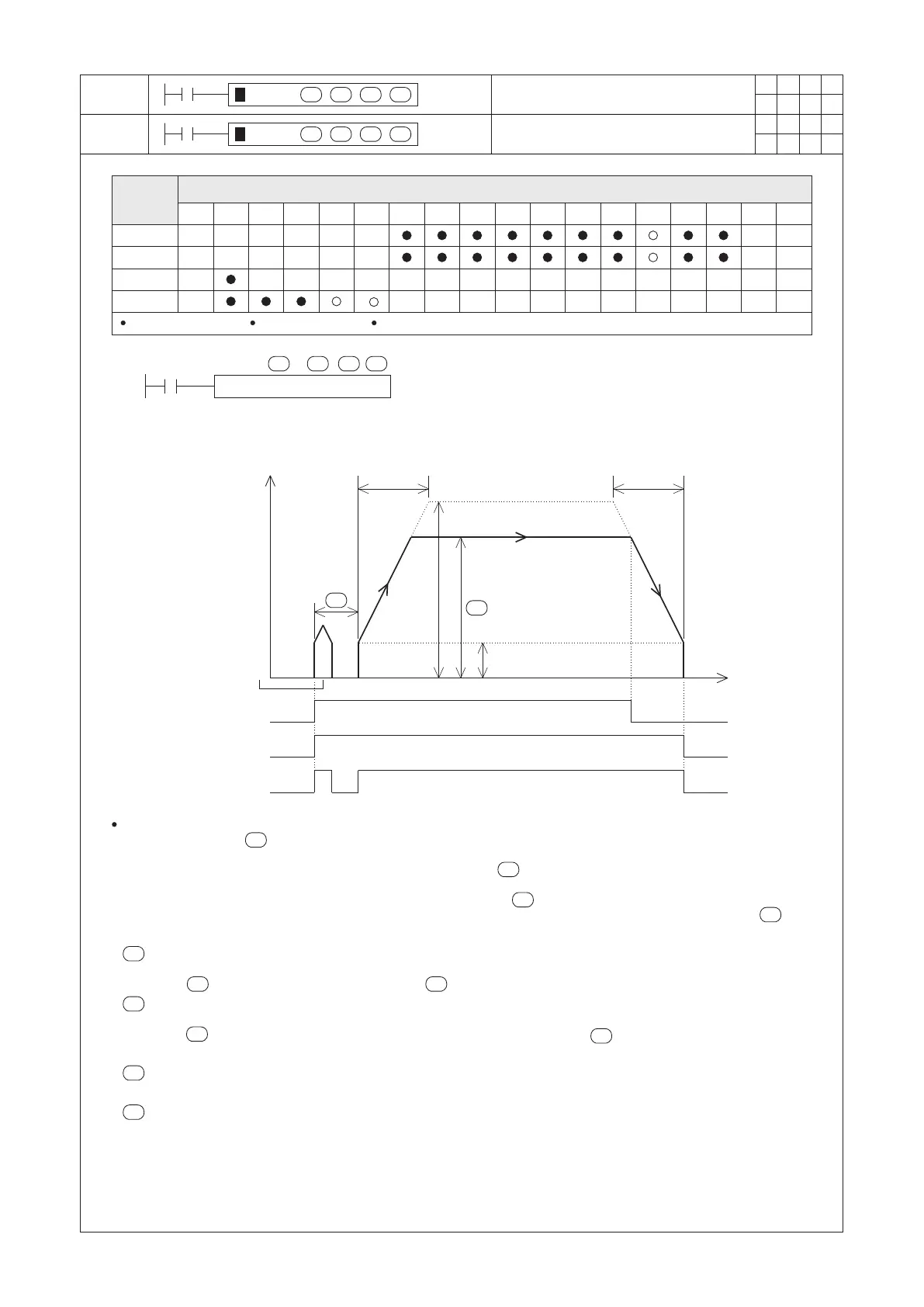
Bias speed (D9342)
Maximum speed
(D9341, D9340)
Deceleration time
(D9344)
Operating speed
S2
S1
One unit of the position
that is user dened
M9340
READY/BUSY Flag
M9341
Pulse output monitor ag
M0
Condition contact
○
○
○
○
Jog Forward
Jog Reverse
Operand
Devices
S1 = 0~5,000
D1 = Y0~Y3
If the D2 is assigned to a Y, it must use Y0~Y7
S1 : the start delay time (Unit: ms.)
S2 : the operating speed (by user unit)
D1 : the output point of generated pulse string
D2 : the output point of direction control signal
Acceleration time
(D9343)
S2
S2
When M0 = “ON”, the Y0 outputs pulse string as the diagram above. During the pulse string generates, the
content value of the can be modied in order to change the operating speed. If the condition contact M0 turns
“OFF” during the pulse string is output, the movement will be gradually slow down then stop.
If the period of the M0 = “ON” is less than the start delay time or the time needed for one unit of the position,
the Y0 will generate the particular number of pulses that is equal to one unit of the position.
If the period of the M0 = “ON” is longer than the start delay time , as the diagram above shows, rst the Y0 will
generate the particular number of pulses that is equal to one unit of the position. After the start delay time is
reached, it begins to generate pulses continually.
is for to assign the start delay time, unit: ms.
The available range is 0~5,000.
When < 0, it will be regarded as 0; when >5,000, it will be regarded as 5,000.
is for to assign the operating speed of JOG.
The available range is from the bias speed (D9342) to the maximum speed (D9341, D9340).
When < the bias speed, it will be regarded as the bias speed; when > the maximum speed, it will be
regarded as the maximum speed.
is for to assign the output point of generated pulse string.
It can only appoint to a point between Y0~Y3, and must use a transistor or line driver output Main Unit.
is for to assign the output point of direction control signal.
When the output of direction control signal is “ON”, the motor moves forward; conversely, “OFF” moves reverse.
Besides, the “ON”/“OFF” status of the direction control signal is decided by the JOGF or JOGR instruction is
executed.
S2
Speed
Time
 Loading...