436
1
2
M
3
○
FNC
304
X Y M S
D.b R.b
KnX KnY
KnM KnS
T C
D,R
V,Z
UnG
K,H
E
" $"
S1
S2
○
D1
D2
D D R V A
S1
S2
D1 D 2
DDRVA D10 D20 Y0 Y4
M0
S1 S2
D1 D2
S1
S1
○ ○
S2
D2
S2
Drive to Absolute Position
Operand
Devices
D1 = Y0~Y3
If the D2 is assigned to a Y, it must use Y0~Y7
S1 : the moving target (by user unit)
S2 : the operating speed (by user unit)
D1 : the output point of generated pulse string
D2 : the output point of direction control signal
S1
S1
S1
S1
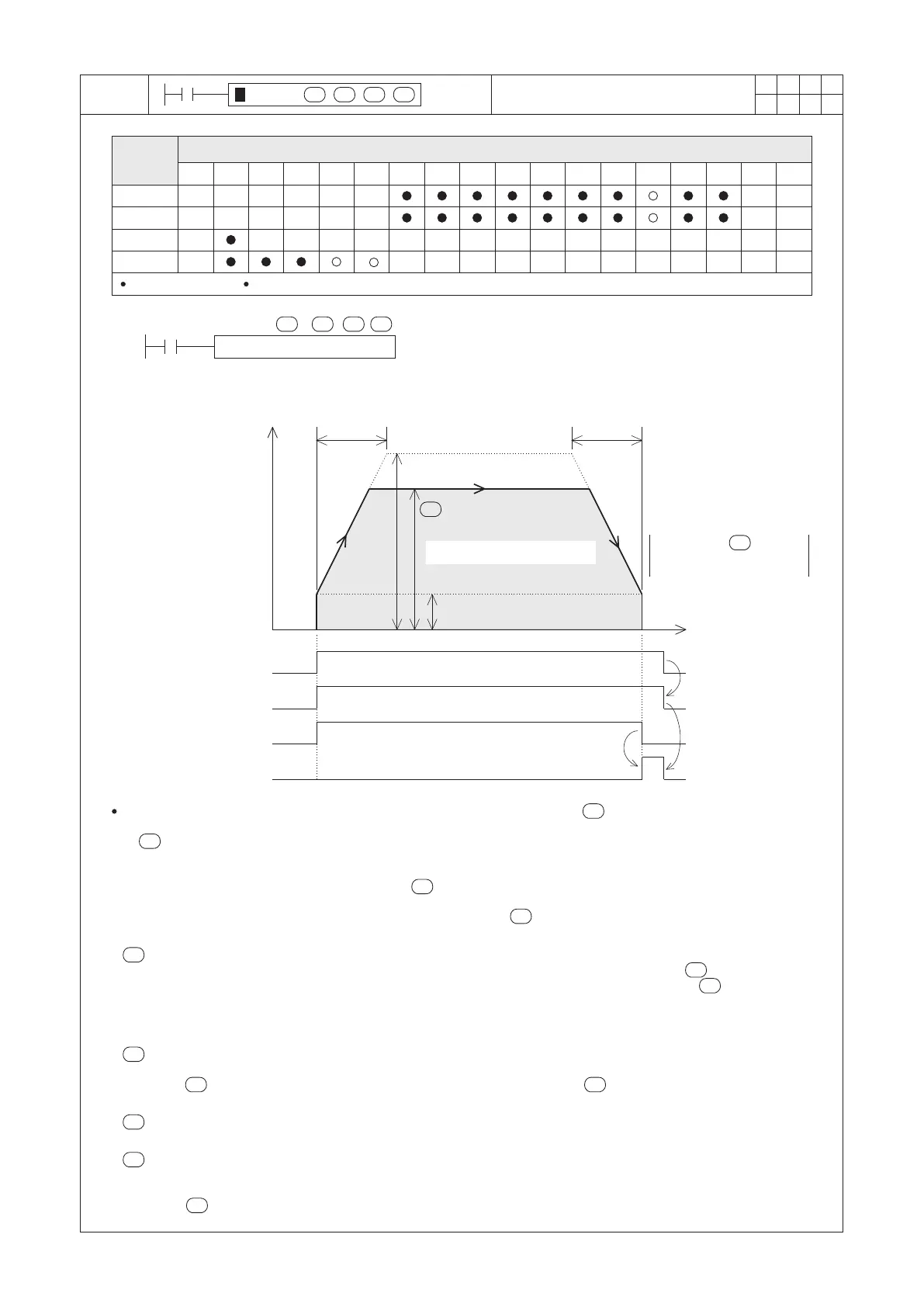
When M0 = “ON”, as the diagram above, the Y0 by the set operating speed to generate the corresponding
number of pulses. That number of pulses is converted from the error (distance to be moved) between the set value
of (D11, D10) and the present value of Y0's position (D9355, D9354). When the positioning action is completed
(to make the PV at D9355, D9354 = D11, D10), it stops to generate pulses.
Assume that the rotational mode “Increase present value when forward” is selected. If the error (distance to be
moved) is a positive number (the moving target > the axis's present value), that needs to increase the present
value, thus the instruction will turn the Y4 “ON” to drive motor moves forward. On the other hand, the error
(distance to be moved) is a negative number (the moving target < the axis's present value), that needs to
decrease the present value, thus the instruction will turn the Y4 “OFF” to drive motor moves backward.
is for to assign the moving target.
This moving target is an absolute point relative to the zero point. If the error is a positive ( − PV > 0) , it will
move in the direction of to increase the present value. Oppositely, if the error is a negative ( − PV < 0), it
will moving in the direction of to decrease the present value. The PLC will convert this moving target to the
pulse unit for the positioning, thus the converted number must meet the range of a 32-bit data. If the converted
value is exceeded this range, the PLC will be regarded that as an operating error and M9067 will be “ON”.
M9342
Positioning completed ag
Bias speed (D9342)
Maximum speed
(D9341, D9340)
Deceleration time
(D9344)
Operating speed
M9340
READY/BUSY Flag
M9341
Pulse output monitor ag
M0
Condition contact
Acceleration time
(D9343)
Speed
Time
S2
D1
S2
is for to assign the operating speed.
The available range is from the bias speed (D9342) to the maximum speed (D9341, D9340).
When < the bias speed, it will be regarded as the bias speed; when > the maximum speed, it will be
regarded as the maximum speed.
is for to assign the output point of generated pulse string.
It can only appoint to a point between Y0~Y3, and must use a transistor or line driver output Main Unit.
S2
is for to assign the output point of direction control signal.
When the output of direction control signal is “ON”, the motor moves forward; conversely, “OFF” moves reverse.
Besides, the “ON”/”OFF” status of the direction control signal is decided by both the +/− numerical value of the
error ( − PV) and the parameter of the rotational direction (increase present value when forward / backward)
are executed.
S1
Distance to be moved (error) =
S1
Moving target
− Y0's PV (DD9354)
Distance to be moved (error)
 Loading...