890370_0•en•01.06.2009
We reserve the right to carry out improvements
22
WAREMA climatronic
®
Installation Instructions
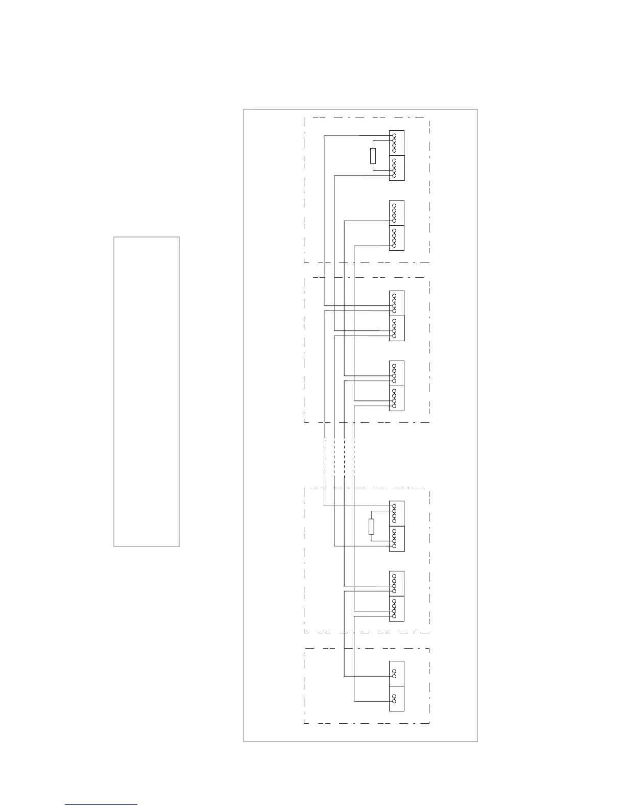
R
- +
Output 24V / 2,5A
Power supply unit Control panelAdditional
devices
Switch actuator Weather station
X5
0V 24V
Supply
ws
ge
X6
A B
RS 485
sw
rt
X5
0V 24V
Supply
ws
ge
X6
A B
RS 485
sw
rt
R
X5
0V 24V
Supply
ws
ge
X6
A B
RS 485
sw
rt
Fig. 7 Basic network structure
CAUTION
The network must be set up according to a line structure with
a 120 Ω terminating resistor on both ends. Star circuits or ring
circuits are not permitted; see Chapter 4.3.
Installation