890370_0•en•01.06.2009 We reserve the right to carry out improvements
25
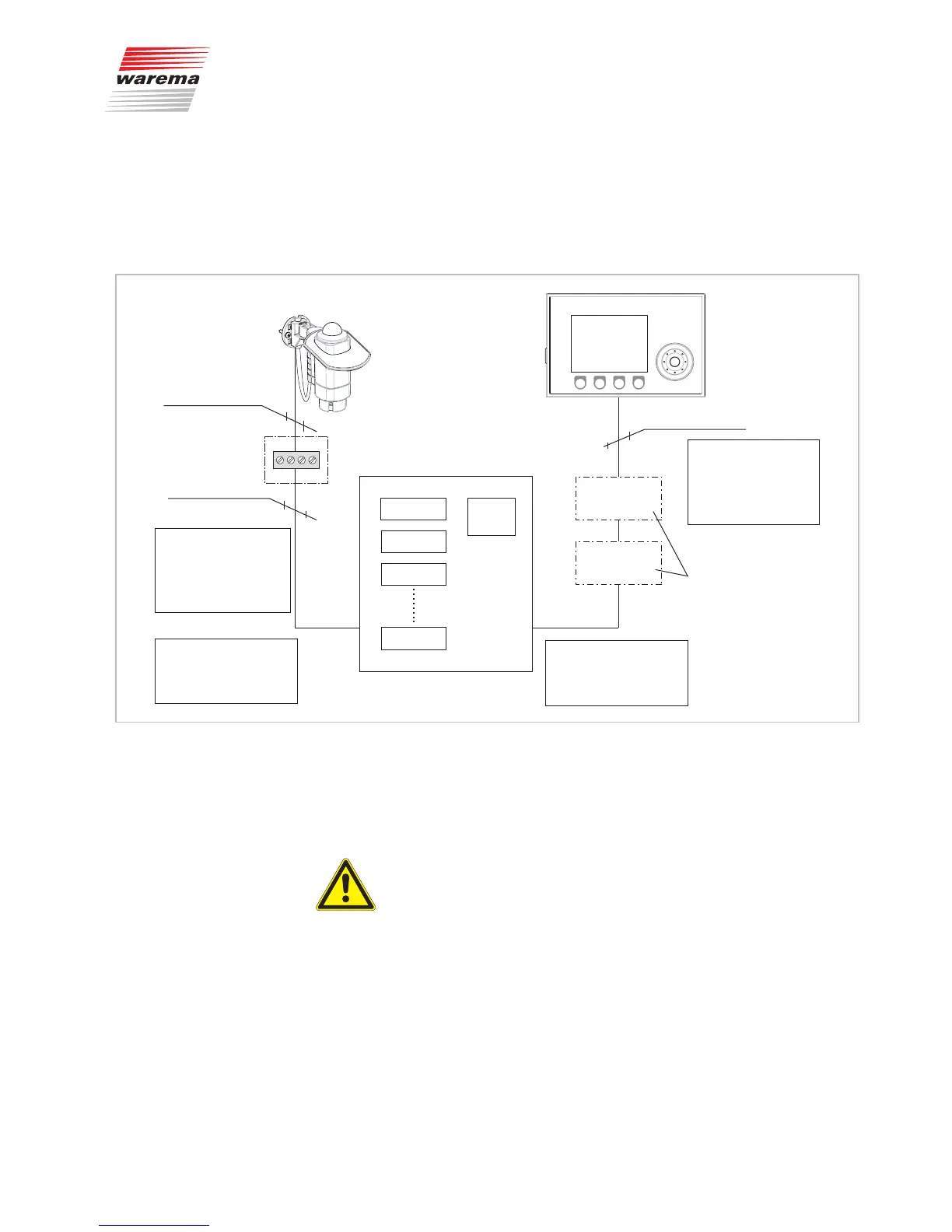
4.3.2 Sizing the power supply
If the actuators (max. 20 per power supply unit) are accommodated in an
equipment cabinet and the weather station, the control panel and up to two
inside temperature and humidity sensors are arranged according to the sche-
matic diagram, you can simply take the maximum cable lengths from the fol-
lowing schematic diagram:
Equipment cabinet
Power
supply unit
24V/2,5A
Actuator 1
Actuator 2
Actuator 3
Actuator 20
Temperature
and humidity sensor 1
Temperature
and humidity sensor 2
Control panel
JY(St)Y 2x2x0,8mm ø
The maximum total line
length between the
control panel and the
equipment cabinet is
200 m!
Weather station
4xAWG 26C UL black
The maximum line length
between the weather
station and the
equipment cabinet
is 150 m.
When using 20 actuators or
more, a separate power
supply unit is required
per 20 devices!
Junction box
JY(St)Y 2x2x0,8mm ø
Optional
The network must have a
line structure. A star or ring
circuit is not permitted!
Fig. 8 Schematic diagram of the standard configuration
The power supply unit required to supply the bus devices delivers an output
current of max. 2.5 A and supplies the network stations with 24 VDC; see
Fig. 7.
CAUTION
However, if the actuators are installed distributed over several rooms, the
maximum permitted cable lengths (total length of line) must be calculated
according to the following formula (see further below) considering the total
current required.
Installation