890370_0•en•01.06.2009
We reserve the right to carry out improvements
26
WAREMA climatronic
®
Installation Instructions
Depending on the number of stations, additional power supply units may be
required. Determine the total power requirements according to the following
table:
Device
Number
(piece)
Current con-
sumption
(mA)
Total current
Control panel 1 170 170
Weather station 250
Inside humidity/temperature sensor 50
Switch actuator 4M/6M 90
Switch actuator 4M230/6M230
—
Dim actuator 2D 50
Sensor interface
Tableau interface
—
Total:
Note the following regarding the table:
The 4M230/6M230 switch actuators are supplied directly via the 230V
mains and do not need to be taken into consideration here.
The current consumption of the sensor interface depends on the number and
type of connected sensors. Determine the current consumption in advance
with the sensors connected or provide a separate power supply unit for the
sensor interface. Information on this can be found in the sensor interface in-
stallation instructions.
The tableau interface must be supplied via a separate power supply unit.
Information on this can be found in the tableau interface installation instruc-
tions.
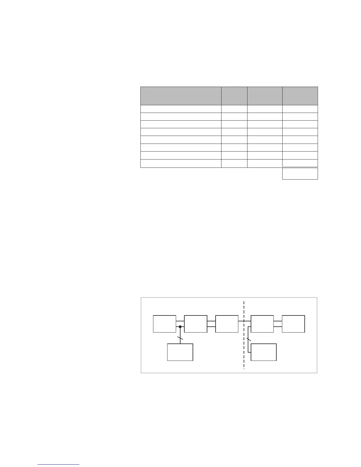
Do not connect the power supply units in parallel. Note the following block
diagram:
Control
panel
Actuator
1
Actuator
2
Actuator
3
Weather-
station
Power
supply unit
1
Power
supply unit
2
2
2
Fig. 9 Block diagram: several power supply units
If a total current of 2.5 A is reached by adding a node (= network device) to
the line, no additional network devices may be connected after this. In this
case, provide an additional power supply unit for a separate section of the
line.
Installation