890370_0•en•01.06.2009 We reserve the right to carry out improvements
27
The voltage may not drop below 20 V at any point, not even at the last de-
vice of the bus. (
UA
<4V)
Also include the length of the line (supply line) or the length of the line sec-
tion in your calculations.
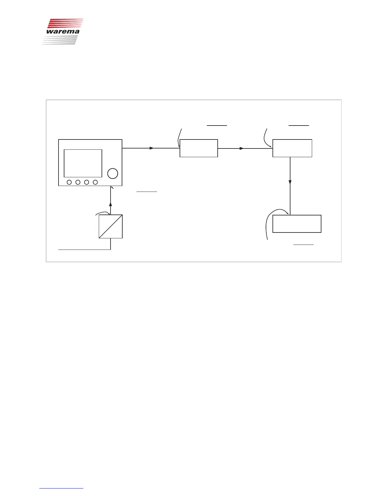
Control panel 170 mA 6M-Actuator 1
90 mA
6M-Actuator 2
90 mA
Weather station
250 mA
L2=20 m
L4=20 m
L3=20 m
L1=10 m
AC
230 V
24 V
DC
U=24 V
U=24 V–
2·L1·I
L1
κ·A
( )
=23,6 V
I
L1
=(170+90+90+250)mA=
600 mA
I
L3
=(90+250)mA=
340 mA
I
L4
=250 mA
I
L2
=(90+90+250)mA=
430 mA
U=23,6 V–
2·L2·I
L2
κ·A
( )
=23 V
U=23 V–
2·L3·I
L3
κ·A
( )
=22,5 V
U=22,5 V–
2·L4·I
L4
κ·A
( )
=22,1 V
Fig. 10 Voltage drops and partial currents
The following formula applies to the voltage drop U
A
on the line:
2 · I
LA
· L
U
A
= --------------------
κ · A
U
A
= Voltage drop on the 24V supply line
L = Single length of line inm
κ = kappa (conductivity, use the value56 for copper)
A = Cross-section of the supply line in mm
2
I
LA
= Current in the line section inA
Preferably, position the power supply unit in the centre of the line or line sec-
tion to minimise the voltage drops. The voltage drop may not be greater than
4V from the power supply unit to the end of the line or line section.
Installation