890370_0•en•01.06.2009 We reserve the right to carry out improvements
21
4.3 Planning the network
structure
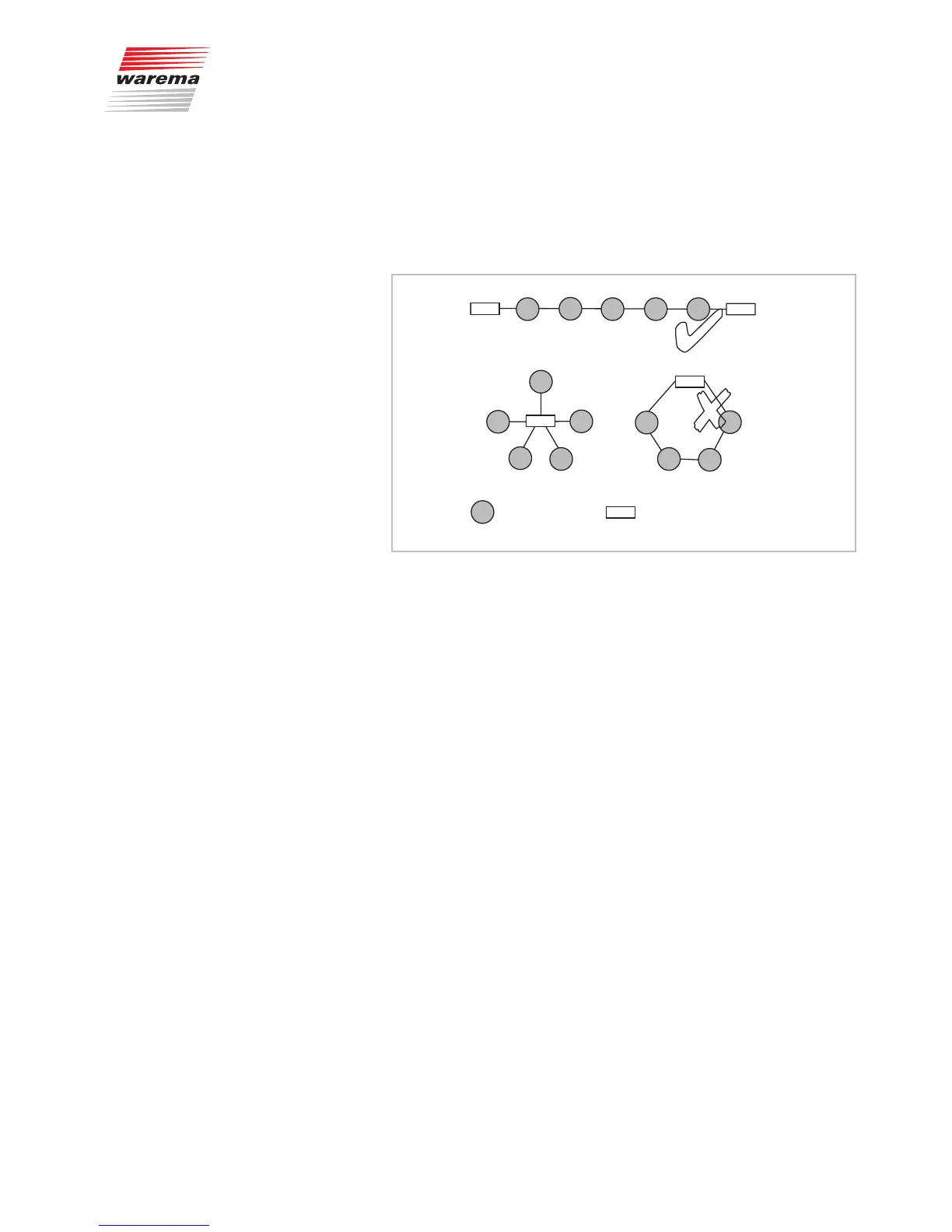
All components of the control communicate with each other via an RS 485
bus system. The structure of the network resembles a line structure. Careful
planning of the network prior to installation saves you elaborate and time-
consuming adjustment work.
= Components
= Terminating resistance
✔
✘
✘
Fig. 6 Bus topology: Do not use start or ring circuits.
Please observe the following items regarding the network structure:
NOTE The control panel should constitute the starting point of the network and the
weather station the terminating point since these two units are equipped with
a factory-activated terminating resistor of 120Ω.
If this arrangement is not possible and a switch actuator or the humidity/tem-
perature sensor constitutes the terminating or starting point of the network,
the starting and terminating point of the bus lines must be concluded with
120Ω. The accessory box includes a suitable bus terminal with an integrated
terminating resistor as well as a single resistor as a spare part.
If the weather station or the control panel is not positioned at the starting
or terminating point of the line, the installed terminating resistor must be re-
moved. On the weather station, it is removed by taking off or switching the
connector (see Fig. 22 on page 43) and on the control panel by using a bus
terminal without an integrated resistor.
The X6(A) and X6(B) bus terminals are used to connect the bus lines. Note
the colour coding of the terminals: do not switch the terminals by mistake.
A maximum of 200 actuators, 3 weather stations and 2 humidity/temperature
sensors may be used in one system.
In case of system malfunction, check whether the bus line has been flaw-
lessly terminated with 120 Ω at both ends.
Also check whether the bus line is correctly connected. The correct polarity
must be adhered to (red and black).
NOTE Observe also Fig. 7 regarding the network arrangement.
Installation