890370_0•en•01.06.2009 We reserve the right to carry out improvements
29
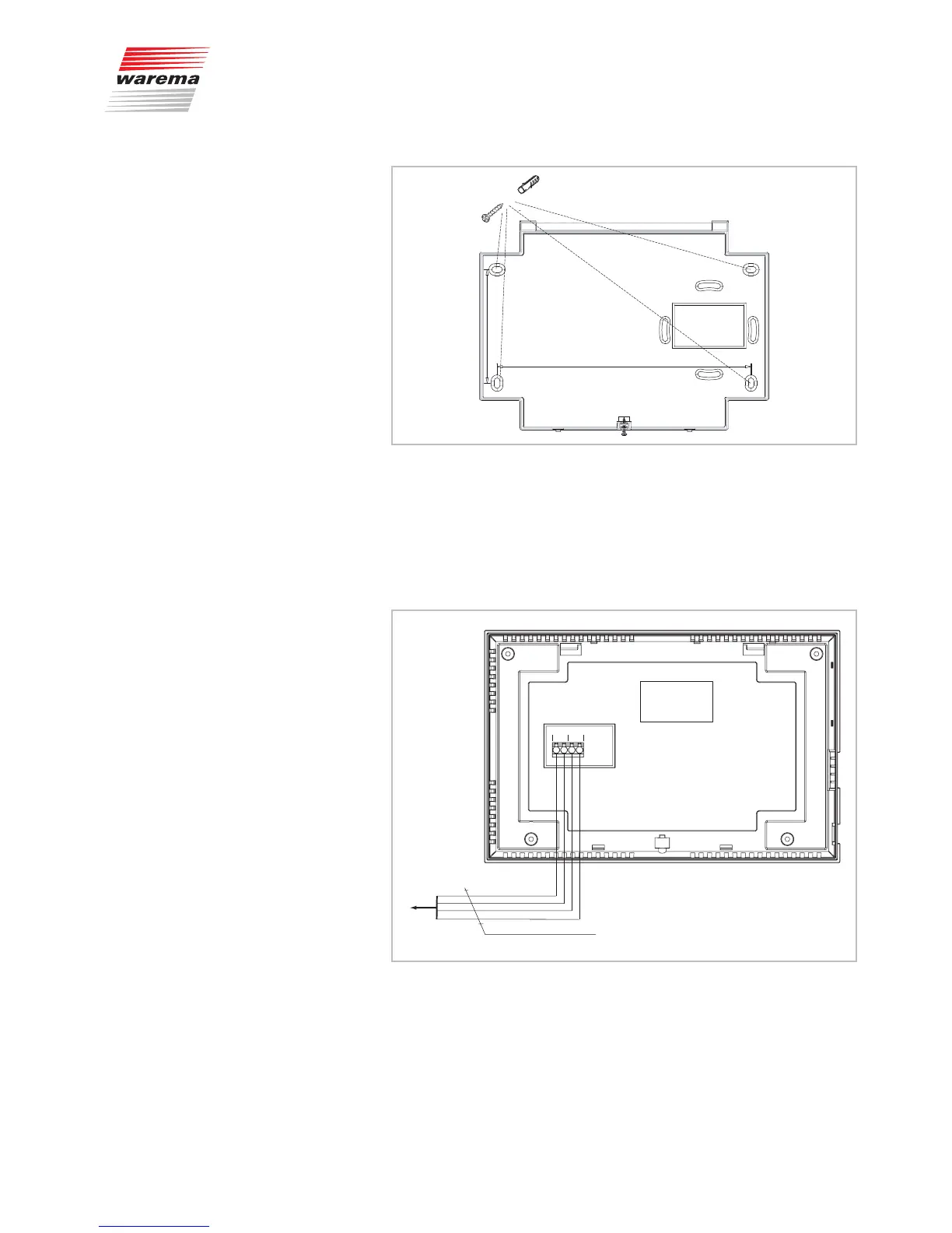
170 mm
76 mm
4x
Fig. 11 Installation of the base plate
NOTE Ensure that the mounting surface is not uneven. The base plate may oth-
erwise become warped and the control panel would not be able to engage
properly.
Connect the individual wires according to the following diagram; observe the
colours of the terminals.
X5
0V
A
B
24V
X6
wt yl
bk
rd
JY(St)Y 2x2x0,8mm ø
wt
yl
bk
rd
to additonal
components
RS 485
Fig. 12 Control panel wiring diagram
Installation