890370_0•en•01.06.2009
We reserve the right to carry out improvements
36
WAREMA climatronic
®
Installation Instructions
123456789
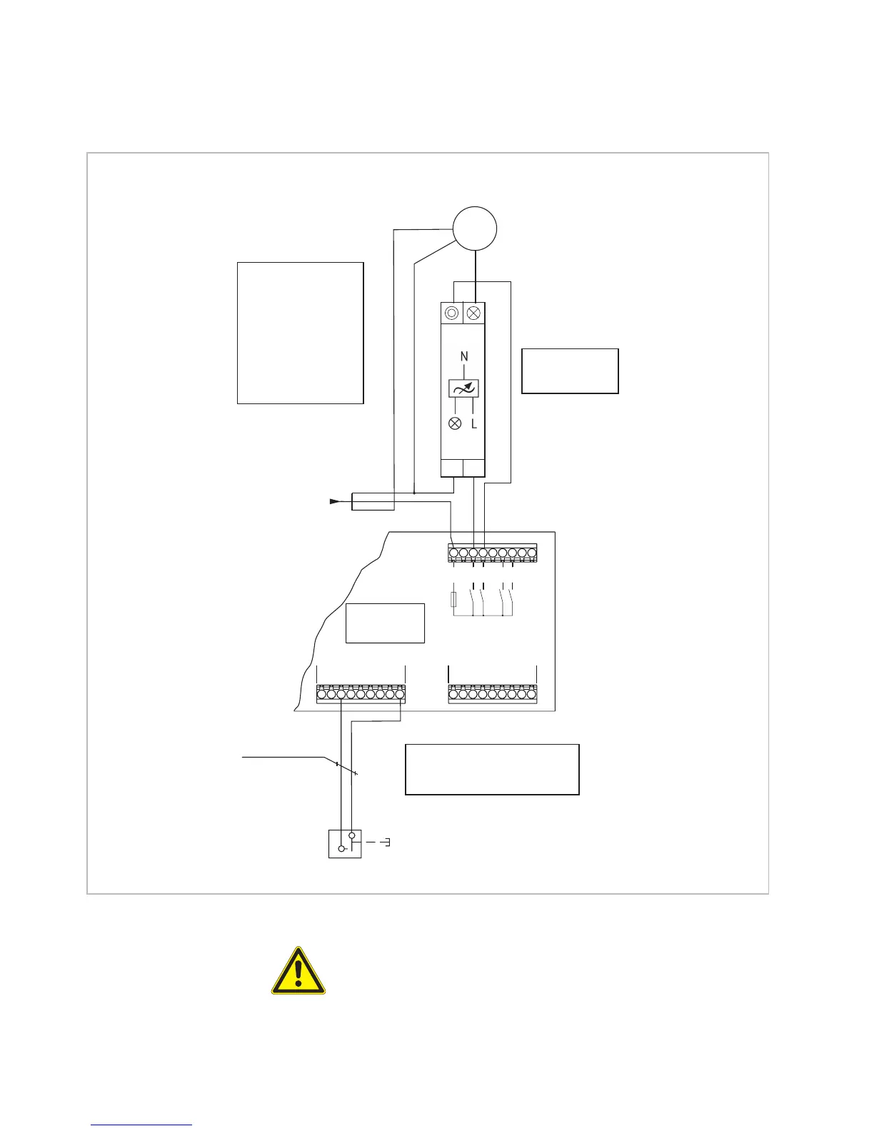
97643
Supply line, onsite
230V AC / 50Hz/16A
3x1,5mm
2
Total current
per supply 15 A
Switch actuator
6M
X8
X4
E
6.2
E
6.1
P
E
5.2
P
E
5.1
E
4.2
E
4.1
ANW
N
L
PE
123456789
X9
PP
V1 V2 V3 V4 V5 V6
GLT
A
5.1
A
5.2
F3
6,3 AT
C
5/6
A
6.1
A
6.2
Pushbutton for dim function
Max. line length
200m
All pushbutton lines
JY(St)Y 2x2x0.8 mm ø
N L
R L C-dimmer
Max. 500 W
Art. no. 1002658
P
1
E 5.2 has no function in
this application
or may not be used!
M
1 ∼
Fan, infinitely variable (external)
You can download the
connection diagrams
and settings for the
fan types of various
manufacturers from
www.warema.de!
N
PE
Fig. 14 Connection example of infinitely variable fan
CAUTION
L loads (inductive loads, e.g. wound transformers) and C loads (capacitive
loads, e.g. electronic control gear) may not be mixed. R loads (ohmic loads,
e.g. 230 V light bulbs and halogen lights) can be added as desired. Only the
specified dimmer, art. no. 1002658, may be used.
Connection information