February 2016
5-1
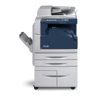
Xerox® WorkCentre® 5945 Family
Parts Lists
5 Parts Lists
PL 1 - Standby Power
PL 1.10 Power and Control Assembly..................
........................................................... 5-3
PL 1.12 Interlock Switches .............................................................................................. 5-4
PL 1.15 Main Power Cables............................................................................................ 5-5
PL 2 - User Interface
PL 2.10 User Interface ..............................
...................................................................... 5-6
PL 3 - Machine Run Control
PL 3.22 Single Board Controller PWB Module................................................................ 5-7
PL 5 - SPDH
PL 5.10 SPDH (Complete), Covers, SPDH PWB............................................................ 5-8
PL 5.17 SPDH Transport Assembly ................................................................................ 5-9
PL 5.18 SPDH Drive Assembly ....................................................................................... 5-10
PL 5.19 SPDH Read Assembly....................................................................................... 5-11
PL 5.20 SPDH Top Cover Assembly............................................................................... 5-12
PL 5.25 SPDH Separation Assembly .............................................................................. 5-13
PL 5.30 Input Tray Assembly .......................................................................................... 5-14
PL 10 - Copy Transportation and Fusing
PL 10.8 Fuser Module ..................................................................................................... 5-15
PL 10.10 Inverter Assembly (1 of 4)................................................................................ 5-16
PL 10.11 Inverter Assembly (Centre Output Tray) (2 of 4).............................................. 5-17
PL 10.12 Inverter Assembly (Horizontal Transport) (3 of 4)............................................ 5-18
PL 10.13 Inverter Assembly (4 of 4)................................................................................ 5-19
PL 10.14 Exit Drive Assembly ......................................................................................... 5-20
PL 10.15 Horizontal Transport Assembly (1 of 2) ........................................................... 5-21
PL 10.16 Horizontal Transport Assembly (2 of 2) ........................................................... 5-22
PL 12 - 2K LCSS
PL 12.10 2K LCSS Covers.............................................................................................. 5-23
PL 12.15 2K LCSS Docking Latch .................................................................................. 5-24
PL 12.20 2K LCSS Hole Punch Unit ............................................................................... 5-25
PL 12.25 2K LCSS Paddle Shaft Assembly .................................................................... 5-26
PL 12.30 2K LCSS Bin 1 Control Components (1 of 2)................................................... 5-27
PL 12.35 2K LCSS Bin 1 Control Components (2 of 2)................................................... 5-28
PL 12.40 2K LCSS Paper Entry Transport...................................................................... 5-29
PL 12.45 2K LCSS Tamper Assembly ............................................................................ 5-30
PL 12.50 2K LCSS Ejector Assembly ............................................................................. 5-31
PL 12.55 2K LCSS Staple Head Unit/Traverse Assembly .............................................. 5-32
PL 12.60 2K LCSS Bin 0 Entry........................................................................................ 5-33
PL 12.65 2K LCSS Bin 1 Entry........................................................................................ 5-34
PL 12.70 2K LCSS Entry Guide Cover/Jam Clearance Guide........................................ 5-35
PL 12.75 2K LCSS Electrical........................................................................................... 5-36
PL 12 - LVF Booklet Maker
PL 12.320 LVF BM - Covers ...........................
................................................................ 5-37
PL 12.325 LVF BM Docking Latch .................................................................................. 5-38
PL 12.330 LVF BM Hole Punch Unit ............................................................................... 5-39
PL 12.335 LVF BM Paddle Shaft Assembly.................................................................... 5-40
PL 12.340 LVF BM Bin 1 Control Components (1 of 2) .................................................. 5-41
PL 12.345 LVF BM Bin 1 Control Components (2 of 2) .................................................. 5-42
PL 12.350 LVF BM Paper Entry Transport...................................................................... 5-43
PL 12.355 LVF BM Tamper Assembly ............................................................................ 5-44
PL 12.360 LVF BM Ejector Assembly ............................................................................. 5-45
PL 12.365 LVF BM Staple Head Unit/Traverse Assembly .............................................. 5-46
PL 12.370 LVF BM Bin 0 Entry ....................................................................................... 5-47
PL 12.375 LVF BM Bin 1 Entry ....................................................................................... 5-48
PL 12.380 LVF BM Booklet Tamper Assembly ............................................................... 5-49
PL 12.385 LVF BM Compiler Entrance Guides............................................................... 5-50
PL 12.390 LVF BM Compiler Guide Assembly ............................................................... 5-51
PL 12.395 LVF BM Booklet Stapler Assembly ................................................................ 5-52
PL 12.400 LVF BM Back Stop Assembly ........................................................................ 5-53
PL 12.405 LVF BM Crease Blade Assembly................................................................... 5-54
PL 12.410 LVF BM Crease Roll Assembly (1 of 3) ......................................................... 5-55
PL 12.415 LVF BM Crease Roll Assembly (2 of 3) ......................................................... 5-56
PL 12.420 LVF BM Crease Roll Assembly (3 of 3) ......................................................... 5-57
PL 12.425 LVF BM Electrical .......................................................................................... 5-58
PL 17 - Secure Access
PL 17.00 Secure Access Additions ....................
............................................................. 5-59
PL 20 - Fax
PL 20.05 Fax Module ...................................................................................................... 5-60
PL 25 - Accessories
PL 25.10 Convenience Stapler........................................................................................ 5-61
PL 26 - Consumables and Tools
PL 26.10 Consumables and Tools (1 of 2).............
......................................................... 5-62
PL 26.11 Consumables and Tools (2 of 2)...................................................................... 5-63
PL 28 - Covers
PL 28.10 Main Covers..................................................................................................... 5-64
PL 28.11 Front Door Assembly ....................................................................................... 5-65
PL 28.15 Covers.............................................................................................................. 5-66
PL 31 - Maintenance/Installation/Removal Kits
PL 31.11 Maintenance/Installation/Removal Kits (1 of 3)................................................ 5-67
PL 31.12 Maintenance/Installation/Removal Kits (2 of 3)................................................ 5-68
PL 31.14 Maintenance/Installation/Removal Kits (3 of 3)................................................ 5-69
PL 31.35 Line 1 Fax Kits ................................................................................................. 5-70
PL 31.40 Line 2 Fax Kits ................................................................................................. 5-71
 Loading...


