PERIODIC MAINTENANCE
3-16
EWA14020
After bleeding the ABS, check the brake op-
eration.
▲▲▲▲ ▲ ▲▲▲▲▲▲▲▲▲ ▲ ▲▲▲▲ ▲ ▲▲▲▲ ▲ ▲▲▲▲▲▲▲
3. Install:
• Right side cover
Refer to “GENERAL CHASSIS” on page 4-1.
EAS21250
CHECKING THE FRONT BRAKE PADS
The following procedure applies to all of the
brake pads.
EC3P61037
The amount of wear may differ for the brake
pads of the right front brake caliper between
the brake pads operated by the brake lever
and the brake pads operated by the brake
pedal. Each set of brake pads should be
checked individually and replaced if neces-
sary.
1. Operate the brake.
2. Check:
• Front brake pad
Wear indicator grooves “1” almost disap-
peared → Replace the brake pads as a set.
Refer to “FRONT BRAKE” on page 4-38.
EAS21190
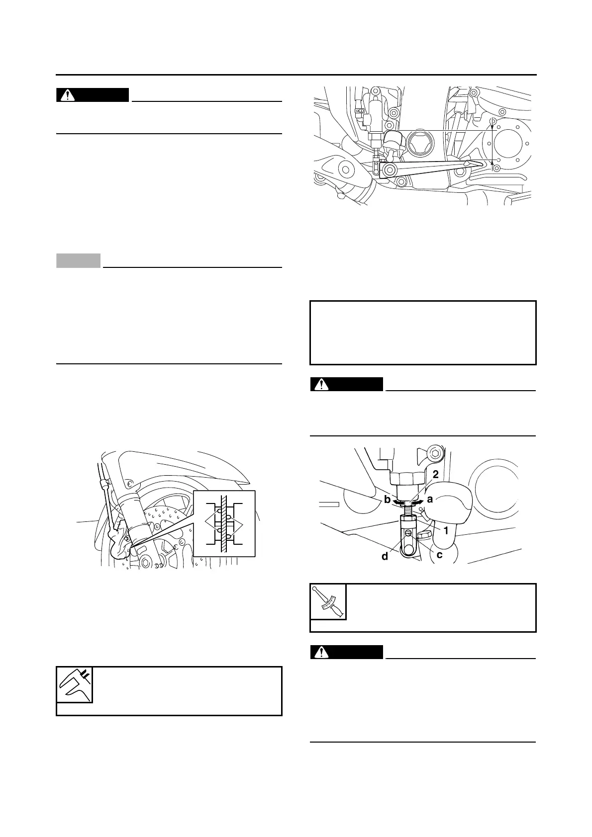
ADJUSTING THE REAR DISC BRAKE
1. Check:
• Brake pedal position
(distance “a” from the top of the rider footrest
to the top of the brake pedal)
Out of specification → Adjust.
2. Adjust:
• Brake pedal position
▼▼▼▼ ▼ ▼▼▼▼▼▼▼▼▼ ▼ ▼▼▼▼ ▼ ▼▼▼▼ ▼ ▼▼▼▼ ▼▼▼
a. Loosen the locknut “1”.
b. Turn the adjusting bolt “2” in direction “a” or
“b” until the specified brake pedal position is
obtained.
EWA13070
After adjusting the brake pedal position,
check that the end of the adjusting bolt “c” is
visible through the hole “d”.
c. Tighten the locknut “1” to specification.
EW3P61002
A soft or spongy feeling in the brake pedal
can indicate the presence of air in the brake
system. Before the vehicle is operated, the
air must be removed by bleeding the brake
system. Air in the brake system will consid-
erably reduce braking performance.
Brake pedal position
42.0 mm (1.65 in) (below the top
of the rider footrest)
Direction “a”
Brake pedal is raised.
Direction “b”
Brake pedal is lowered.
Rear brake master cylinder lock-
nut
16 Nm (1.6 m·kg, 11 ft·lb)
a