SHAFT DRIVE
4-114
▲▲▲▲ ▲ ▲▲▲▲▲▲▲▲▲ ▲ ▲▲▲▲ ▲ ▲▲▲▲ ▲ ▲▲▲▲▲▲▲
EAS23600
MEASURING THE RING-GEAR-TO-
STOPPER-BOLT CLEARANCE
1. Remove:
• Ring gear bearing housing
(along with the ring gear)
Refer to “ADJUSTING THE FINAL GEAR
BACKLASH” on page 4-113.
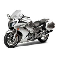
2. Measure:
• Ring-gear-to-stopper-bolt clearance “a”
Out of specification → Adjust.
3. Install:
• Ring gear bearing housing
(along with the ring gear)
EAS23610
ADJUSTING THE RING-GEAR-TO-
STOPPER-BOLT CLEARANCE
1. Remove:
• Ring gear “1”
• Stopper bolt “2”
• Stopper bolt shim(s) “3”
• Ring gear bearing housing “4”
2. Select:
• Stopper bolt shim(s)
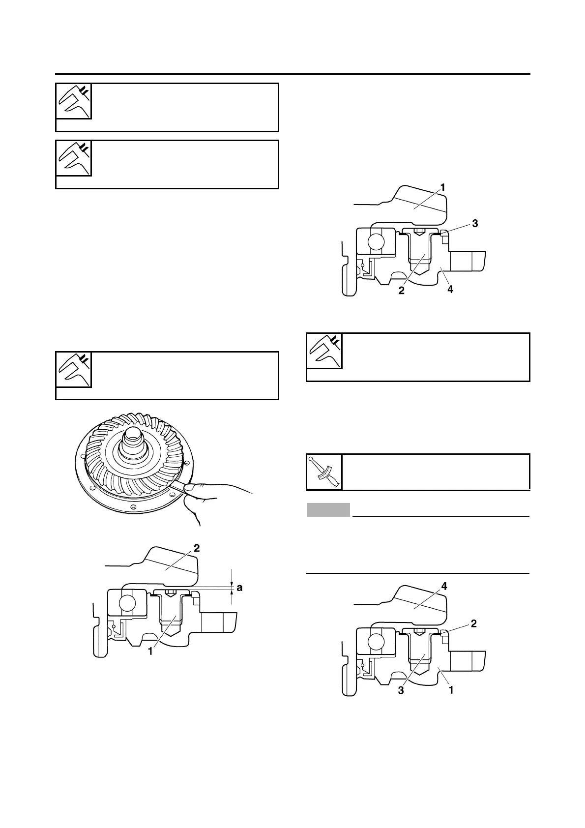
3. Install:
• Ring gear bearing housing “1”
• Stopper bolt shim(s) “2”
• Stopper bolt “3”
• Ring gear “4”
ECA14320
• The stopper bolt has left-hand threads. To
tighten the stopper bolt, turn it counter-
clockwise.
• Apply LOCTITE® onto the stopper bolt.
4. Measure:
• Ring-gear-to-stopper-bolt clearance
Ring gear shims
Thickness (mm)
0.25 0.30 0.40 0.50
Thrust washers
Thickness (mm)
1.2 1.4 1.6 1.8 2.0
Ring-gear-to-stopper-bolt clear-
ance
0.30–0.60 mm (0.0118–0.0236 in)
1. Stopper bolt
2. Ring gear
Stopper bolt shims
Thickness (mm)
0.15 0.20
Stopper bolt
9 Nm (0.9 m·kg, 6.5 ft·lb)