TRANSMISSION
5-103
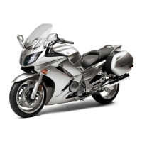
2. Measure:
• Drive axle runout
(with a centering device and dial gauge “1”)
Out of specification → Replace the drive axle.
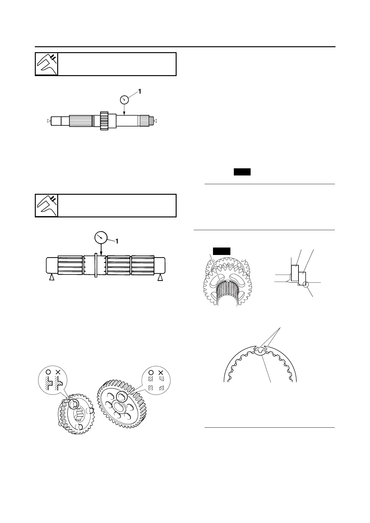
3. Check:
• Transmission gears
Blue discoloration/pitting/wear → Replace
the defective gear(s).
• Transmission gear dogs
Cracks/damage/rounded edges → Replace
the defective gear(s).
4. Check:
• Transmission gear engagement
(each pinion gear to its respective wheel
gear)
Incorrect → Reassemble the transmission
axle assemblies.
5. Check:
• Transmission gear movement
Rough movement → Replace the defective
part(s).
6. Check:
• Circlips
Bends/damage/looseness → Replace.
ET3P61030
ASSEMBLING THE MAIN AXLE AND DRIVE
AXLE
1. Install:
• Toothed washer “1”
• Circlip “2”
• Be sure the circlip sharp-edged corner “a” is
positioned opposite side to the toothed washer
and gear. (For main axle)
• Install the circlip so that both ends “b” rest on
the sides of a spline “c” with both axles aligned.
2. Install:
• Toothed lock washer retainer “1”
• Toothed lock washer “2”
• With the toothed lock washer retainer “1” in the
groove “a” in the axle, align the projection on
the retainer with an axle spline, and then install
the toothed lock washer “2”.
Main axle runout limit
0.08 mm (0.0032 in)
Drive axle runout limit
0.08 mm (0.0032 in)