SHAFT DRIVE
4-119
6. Adjust:
• Final gear backlash
Refer to “MEASURING THE FINAL GEAR
BACKLASH” on page 4-112 and “ADJUST-
ING THE FINAL GEAR BACKLASH” on
page 4-113.
7. Measure:
• Ring-gear-to-thrust-washer clearance
▼▼▼▼ ▼ ▼▼▼▼▼▼▼▼▼ ▼ ▼▼▼▼ ▼ ▼▼▼▼ ▼ ▼▼▼▼▼▼▼
a. Remove the ring gear bearing housing (along
with the ring gear).
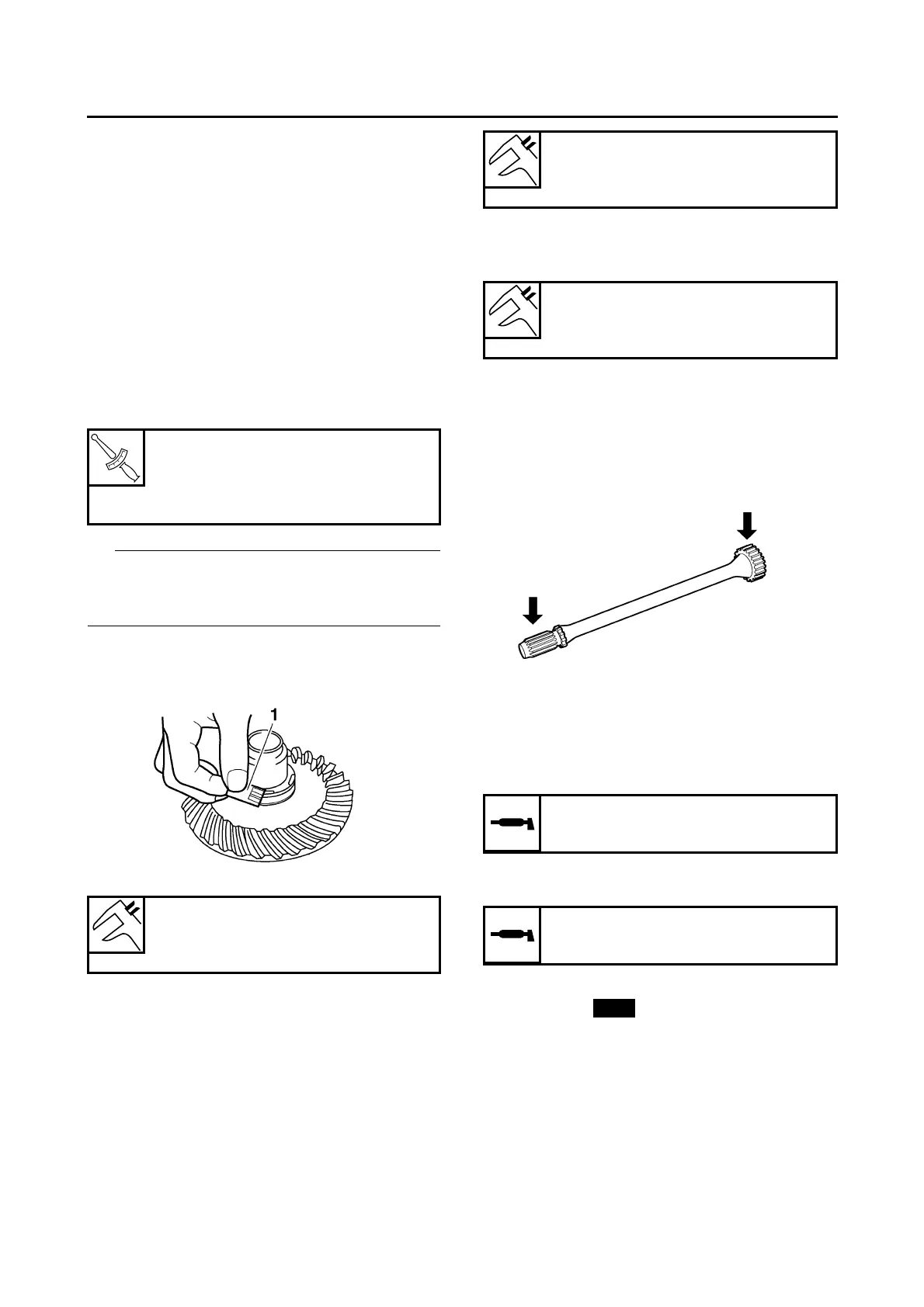
b. Place four pieces of Plastigauge® between
the original thrust washer and the ring gear.
c. Install the ring gear bearing housing and
tighten the bolts and nuts to specification.
Do not turn the final drive pinion gear and ring
gear while measuring the ring-gear-to-thrust-
washer clearance with Plastigauge®.
d. Remove the ring gear bearing housing.
e. Measure the width of the flattened Plasti-
gauge® “1”.
f. If the ring-gear-to-thrust-washer clearance is
within specification, install the ring gear bear-
ing housing (along with the ring gear).
g. If the ring-gear-to-thrust-washer clearance is
out of specification, select the correct thrust
washer as follows.
h. Select the suitable thrust washer from the fol-
lowing chart.
i. Repeat the measurement steps until the ring-
gear-to-thrust-washer clearance is within the
specified limits.
▲▲▲▲ ▲ ▲▲▲▲▲▲▲▲▲ ▲ ▲▲▲▲ ▲ ▲▲▲▲ ▲ ▲▲▲▲ ▲▲▲
EAS23650
CHECKING THE DRIVE SHAFT
1. Check:
• Drive shaft splines
Damage/wear → Replace the drive shaft.
EAS23660
INSTALLING THE DRIVE SHAFT AND FINAL
DRIVE ASSEMBLY
1. Lubricate:
• Drive shaft spline (final drive pinion gear side)
2. Lubricate:
• Drive shaft spline (universal joint side)
3. Install:
• Oil seal “1”
• Washer “2”
(with the fork seal driver weight “3” and fork
seal driver attachment “4”)
Ring gear bearing housing bolt
40 Nm (4.0 m·kg, 29 ft·lb)
Ring gear bearing housing nut
23 Nm (2.3 m·kg, 17 ft·lb)
Ring-gear-to-thrust-washer clear-
ance
0.20 mm (0.0079 in)
Thrust washers
Thickness (mm)
1.2 1.4 1.6 1.8 2.0
Ring-gear-to-thrust-washer clear-
ance
0.20 mm (0.0079 in)
Recommended lubricant
Molybdenum disulfide grease
Recommended lubricant
Lithium-soap-based grease