SHAFT DRIVE
4-120
4. Install:
• Circlip
5. Install:
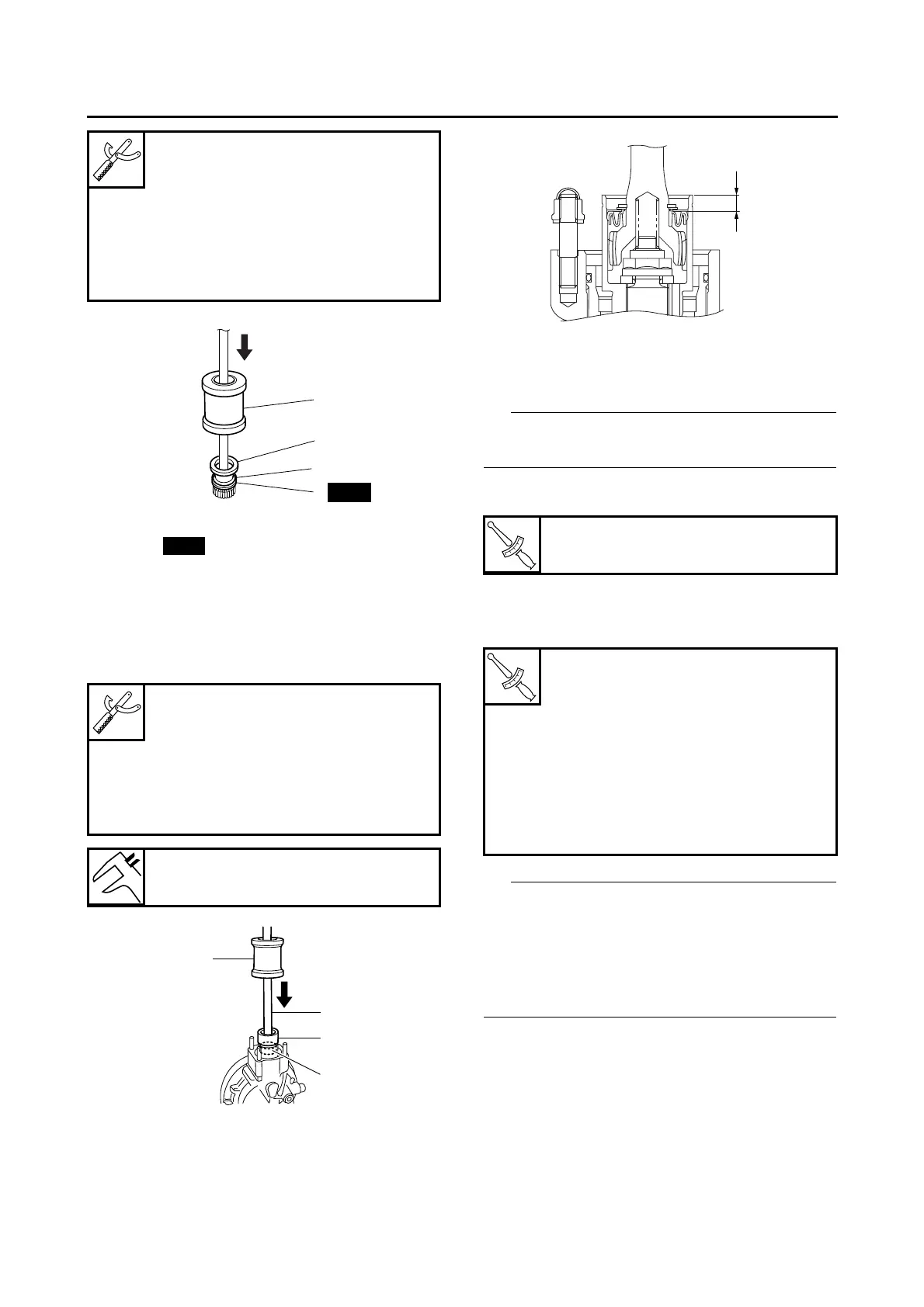
• Drive shaft “1”
(to the final drive pinion gear)
• Oil seal “2”
(to the final gear case with the fork seal driver
weight “3” and oil seal installing tool “4”)
6. Install:
• Universal joint
• Final drive assembly
Align the drive shaft splines with the driven yoke
of the universal joint.
7. Tighten:
• Final drive assembly nuts
8. Install:
• Sidestand
• Left footrest assembly
Install the left footrest assembly and sidestand
bolts “1”, left footrest assembly bolts (M8) “2”
and left footrest assembly bolt (M10) “3” tempo-
rarily and then tighten them to the specified
torques in the proper tightening sequence as
shown.
Fork seal driver weight
90890-01184
Replacement hammer
YM-A9409-7
Fork seal driver attachment
90890-01186
Replacement 27 mm
YM-A9409-1
Fork seal driver weight
90890-01184
Replacement hammer
YM-A9409-7
Oil seal installing tool
90890-01512
YM-01512
Installed depth “a”
8.5–10.0 mm (0.33–0.39 in)
Final drive assembly nut
42 Nm (4.2 m·kg, 30 ft·lb)
Left footrest assembly and side-
stand bolt
65 Nm (6.5 m·kg, 47 ft·lb)
LOCTITE®
Left footrest assembly bolt (M8)
28 Nm (2.8 m·kg, 20 ft·lb)
LOCTITE®
Left footrest assembly bolt (M10)
49 Nm (4.9 m·kg, 35 ft·lb)
LOCTITE®