REAR WHEEL
4-34
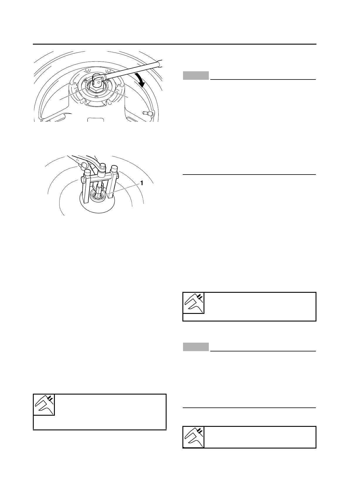
d. Remove the wheel sensor rotor.
e. Remove the wheel bearings “1” with a gener-
al bearing puller.
▲▲▲▲ ▲ ▲▲▲▲▲▲▲▲▲ ▲ ▲▲▲▲ ▲ ▲▲▲▲ ▲ ▲▲▲▲▲▲▲
EAS22090
CHECKING THE REAR WHEEL
1. Check:
• Rear wheel axle
• Rear wheel
• Wheel bearings
• Oil seal
Refer to “CHECKING THE FRONT WHEEL”
on page 4-25.
2. Check:
•Tire
• Rear wheel
Damage/wear → Replace.
Refer to “CHECKING THE TIRES” on page
3-17 and “CHECKING THE WHEELS” on
page 3-17.
3. Measure:
• Radial wheel runout
• Lateral wheel runout
Refer to “CHECKING THE FRONT WHEEL”
on page 4-25.
EAS22200
MAINTENANCE OF THE REAR WHEEL
SENSOR AND SENSOR ROTOR
ECA3P6D008
• Handle the ABS components with care
since they have been accurately adjusted.
Keep them away from dirt and do not sub-
ject them to shocks.
• The rear wheel sensor cannot be disassem-
bled. Do not attempt to disassemble it. If
faulty, replace with a new one.
• Keep magnets (including magnetic pick-up
tools, magnetic screwdrivers, etc.) away
from the wheel sensor rotor.
• Do not drop or shock the wheel sensor or
the wheel sensor rotor.
1. Check:
• Rear wheel sensor
Refer to “MAINTENANCE OF THE FRONT
WHEEL SENSOR AND SENSOR ROTOR”
on page 4-26.
2. Check:
• Rear wheel sensor rotor
Refer to “MAINTENANCE OF THE FRONT
WHEEL SENSOR AND SENSOR ROTOR”
on page 4-26.
3. Measure:
• Rear wheel sensor rotor deflection
Refer to “MAINTENANCE OF THE FRONT
WHEEL SENSOR AND SENSOR ROTOR”
on page 4-26.
EAS22140
ASSEMBLING THE REAR WHEEL
ECA3P6D003
• Keep magnets (including magnetic pick-up
tools, magnetic screwdrivers, etc.) away
from the wheel sensor rotor.
• Do not drop the wheel sensor rotor or sub-
ject it to shocks.
• If any solvent gets on the wheel sensor ro-
tor, wipe it off immediately.
1. Install:
• Bearing “1”
Radial wheel runout limit
1.0 mm (0.04 in)
Lateral wheel runout limit
0.5 mm (0.02 in)
Wheel sensor rotor deflection
limit
0.14 mm (0.0055 in)
Installed depth of bearing “a”
3.5–4.5 mm (0.14–0.18 in)