CAMSHAFTS
5-11
EAS23760
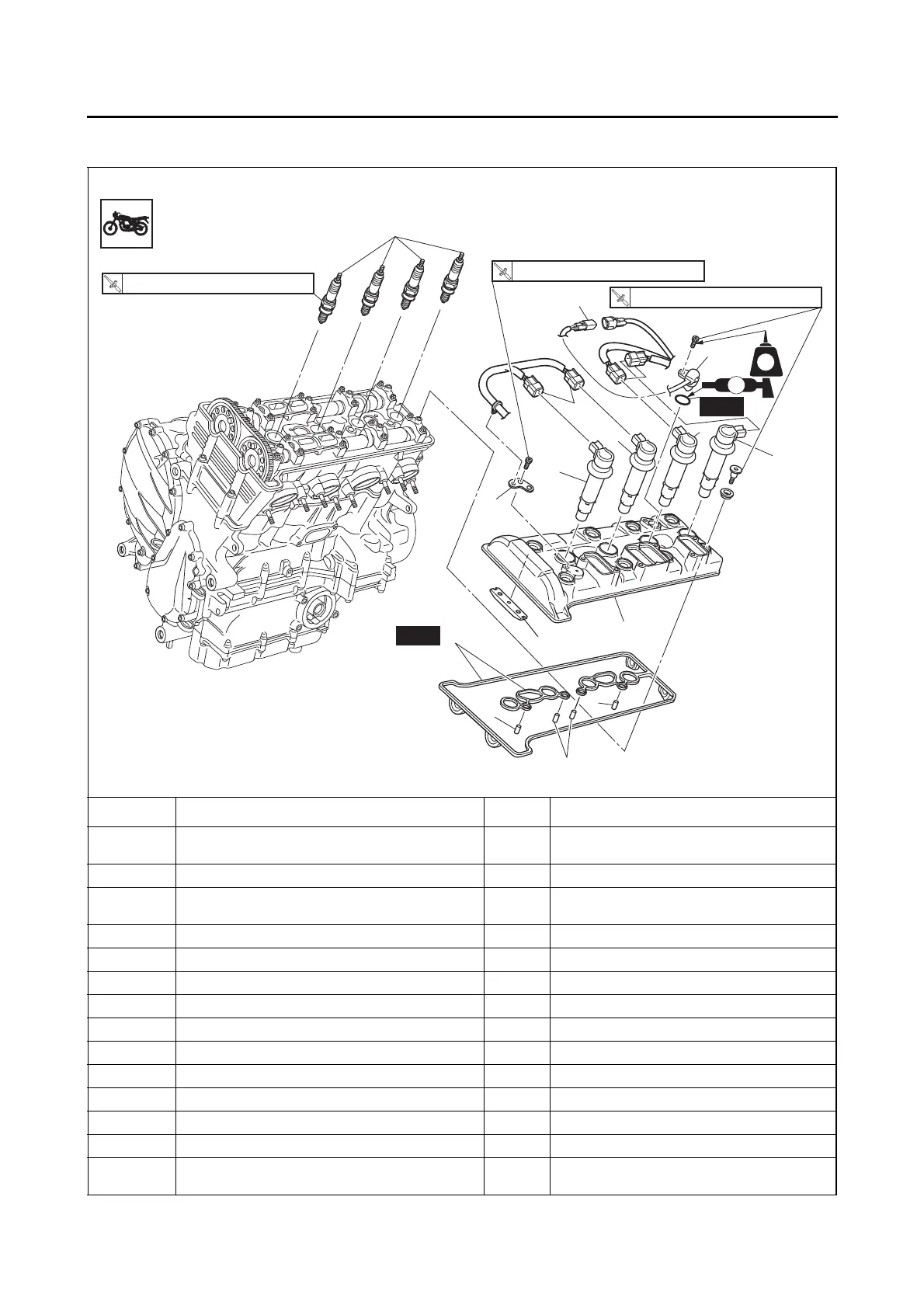
CAMSHAFTS
Removing the cylinder head cover
Order Job/Parts to remove Q’ty Remarks
T- b a r
Refer to “GENERAL CHASSIS” on page
4-1.
Thermostat inlet pipe 1 Refer to “THERMOSTAT” on page 6-6.
Air cut-off valve/Reed valves
Refer to “AIR INDUCTION SYSTEM” on
page 7-13.
1 Ignition coil coupler 4 Disconnect.
2 Cylinder head cover plate 1
3 Cylinder identification sensor coupler 1 Disconnect.
4 Ignition coil 4
5 Cylinder identification sensor 1
6 Spark plug 4
7 Cylinder head cover 1
8 Cylinder head cover gasket 1
9 Dowel pin 4
10 Timing chain guide (upper side) 1
For installation, reverse the removal proce-
dure.
New
6
New
8
9
9
9
5
3
(8)
10
7
T
R
.
.
10 Nm (1.0 m
•
kg, 7.2 ft
•
Ib)
T
R
.
.
10 Nm (1.0 m
•
kg, 7.2 ft
•
Ib)
4
2
4
1
1
4
4
LT
LS
T
R
.
.
13 Nm (1.3 m
•
kg, 9.4 ft
•
Ib)