PERIODIC MAINTENANCE
3-5
10.Install:
• T-bar
Refer to “GENERAL CHASSIS” on page 4-1.
• Fuel tank
Refer to “FUEL TANK” on page 7-1.
• Rider seat
Refer to “GENERAL CHASSIS” on page 4-1.
EAS20490
ADJUSTING THE VALVE CLEARANCE
The following procedure applies to all of the
valves.
• Valve clearance adjustment should be made
on a cold engine, at room temperature.
• When the valve clearance is to be measured or
adjusted, the piston must be at top dead center
(TDC) on the compression stroke.
1. Remove:
• Rider seat
• Right side cowling
Refer to “GENERAL CHASSIS” on page 4-1.
• Fuel tank
Refer to “FUEL TANK” on page 7-1.
• T-bar
Refer to “GENERAL CHASSIS” on page 4-1.
• Air cut-off valve
Refer to “AIR INDUCTION SYSTEM” on
page 7-13.
• Thermostat inlet pipe 1
Refer to “THERMOSTAT” on page 6-6.
2. Remove:
• Spark plugs
• Cylinder head cover
• Cylinder head cover gasket
Refer to “CAMSHAFTS” on page 5-11.
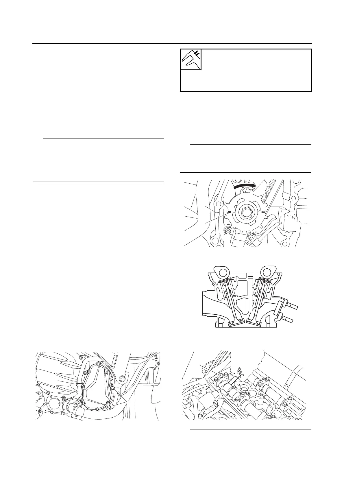
3. Remove:
• Hose holder “1”
• Lead holders “2”
• Pickup rotor cover “3”
4. Measure:
• Valve clearance
Out of specification → Adjust.
▼▼▼▼ ▼ ▼▼▼▼▼▼▼▼▼ ▼ ▼▼▼▼ ▼ ▼▼▼▼ ▼ ▼▼▼▼ ▼▼▼
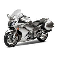
a. Turn the crankshaft clockwise.
b. When piston #1 is at TDC on the compres-
sion stroke, align the TDC mark “a” on the
pickup rotor with the crankcase mating sur-
face “b”.
TDC on the compression stroke can be found
when the camshaft lobes are turned away from
each other.
c. Measure the valve clearance with a thickness
gauge “1”.
• If the valve clearance is incorrect, record the
measured reading.
Valve clearance (cold)
Intake
0.15–0.22 mm (0.0059–0.0087 in)
Exhaust
0.18–0.25 mm (0.0071–0.0098 in)
1