THROTTLE BODIES
7-9
5. Adjust:
• Throttle bodies synchronizing
Out of specification → Replace the throttle
bodies.
Refer to “SYNCHRONIZING THE THROT-
TLE BODIES” on page 3-8.
EAS21010
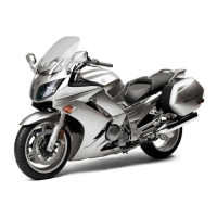
CHECKING THE THROTTLE BODY JOINTS
1. Check:
• Throttle body joints “1”
Cracks/damage → Replace.
EAS1MC1067
REPLACING THE THROTTLE BODIES
1. Remove the throttle bodies from the vehicle.
2. Install a new throttle bodies to the vehicle.
3. Reset:
• ISC (idle speed control) learning values
Use the diagnostic code number “67”.
Refer to “SELF-DIAGNOSTIC FUNCTION
AND DIAGNOSTIC CODE TABLE” on page
9-5.
4. Adjust:
• Throttle bodies synchronizing
Refer to “SYNCHRONIZING THE THROT-
TLE BODIES” on page 3-8.
5. Place the vehicle on the centerstand so that
the rear wheel is elevated.
6. Check:
• Engine idling speed
Start the engine, warm it up, and then mea-
sure the engine idling speed.
EAS1MC1073
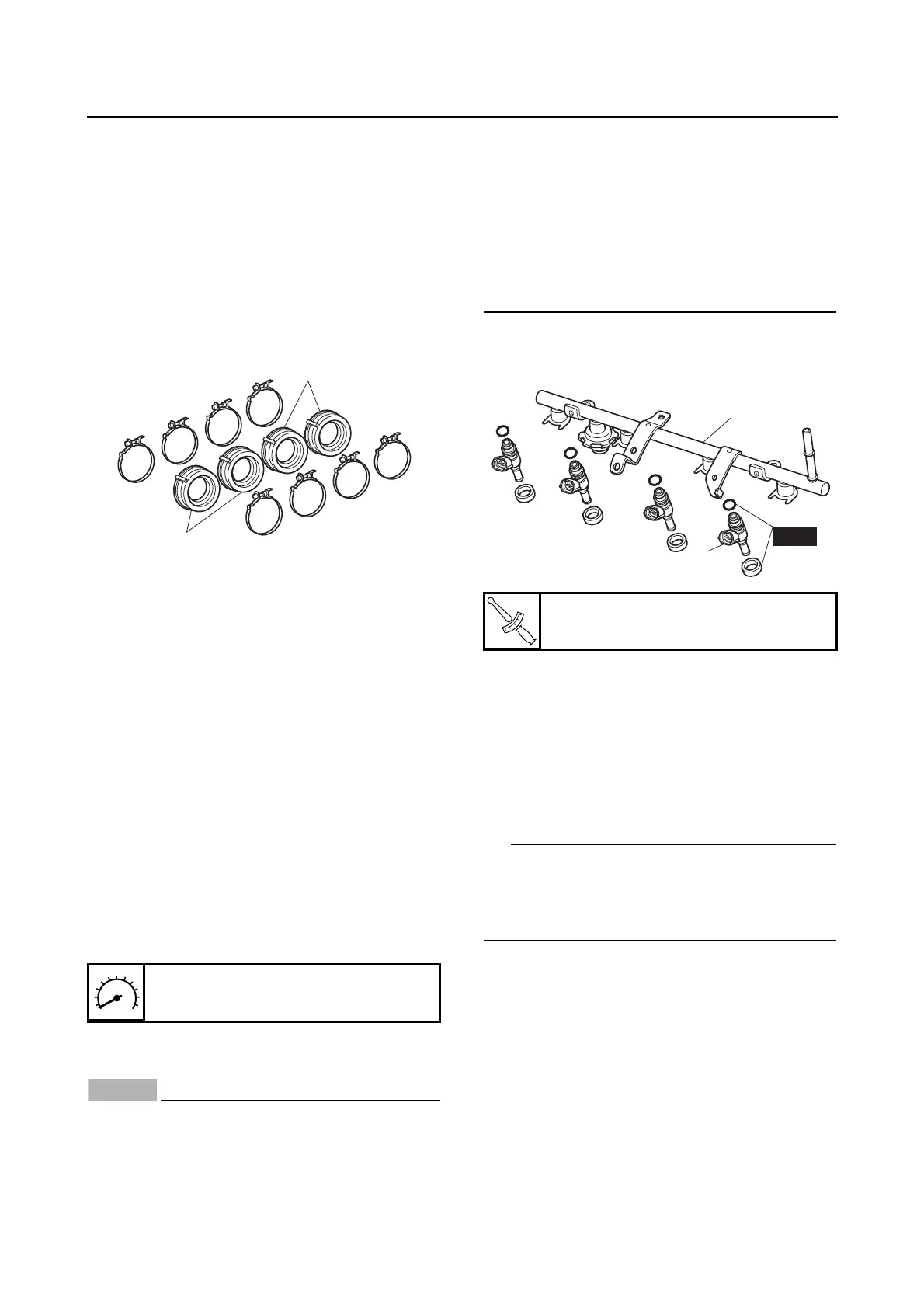
INSTALLING THE INJECTORS
ECA1MC1022
• Always use new O-rings and seals.
• When checking the injectors, do not allow
any foreign material to enter or adhere to
the injectors, fuel rail, O-rings, or seals.
• Be careful not to twist or pinch the O-rings
when installing the injectors.
• If an injector is subject to strong shocks or
excessive force, replace it.
• If installing the original fuel rail and screws,
remove the white paint marks using a
cleaning solvent. Otherwise, paint chips on
the screw seats could prevent the screws
from being tightened.
1. Install new O-rings and seals onto the end of
each injector.
2. Install the injectors “1” to the fuel rail “2”.
3. Install the injector assemblies to the throttle
bodies.
4. Check the injector pressure after the injectors
are installed to the throttle bodies.
Refer to “CHECKING THE INJECTOR
PRESSURE” on page 7-9.
EAS1MC1074
CHECKING THE INJECTOR PRESSURE
• After installing the injectors, perform the follow-
ing steps to check the injector pressure.
• Do not allow any foreign materials to enter the
fuel lines.
1. Check:
• Injector pressure
▼▼▼▼ ▼ ▼▼▼▼▼▼▼▼▼ ▼ ▼▼▼▼ ▼ ▼▼▼▼ ▼ ▼▼▼▼ ▼▼▼
a. Connect the injector pressure adapter “1” to
the fuel rail “2”, and then connect an air com-
pressor “3” to the adapter.
b. Connect the pressure gauge “4” to the injec-
tor pressure adapter “1”.
Engine idling speed
1000–1100 r/min
Fuel rail screw
5 Nm (0.5 m·kg, 3.6 ft·lb)
2
1
New