CONNECTING RODS AND PISTONS
5-90
e. Tighten the connecting rod nuts.
Refer to “INSTALLING THE CONNECTING
RODS AND PISTONS” on page 5-90.
f. Remove the connecting rod and big end
bearings.
Refer to “REMOVING THE CONNECTING
RODS AND PISTONS” on page 5-86.
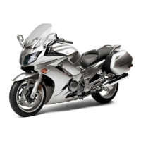
g. Measure the compressed Plastigauge®
width “e” on the crankshaft pin.
If the crankshaft-pin-to-big-end-bearing
clearance is out of specification, select re-
placement big end bearings.
▲▲▲▲ ▲ ▲▲▲▲▲▲▲▲▲ ▲ ▲▲▲▲ ▲ ▲▲▲▲ ▲ ▲▲▲▲▲▲▲
2. Select:
• Big end bearings (P
1
–P
4
)
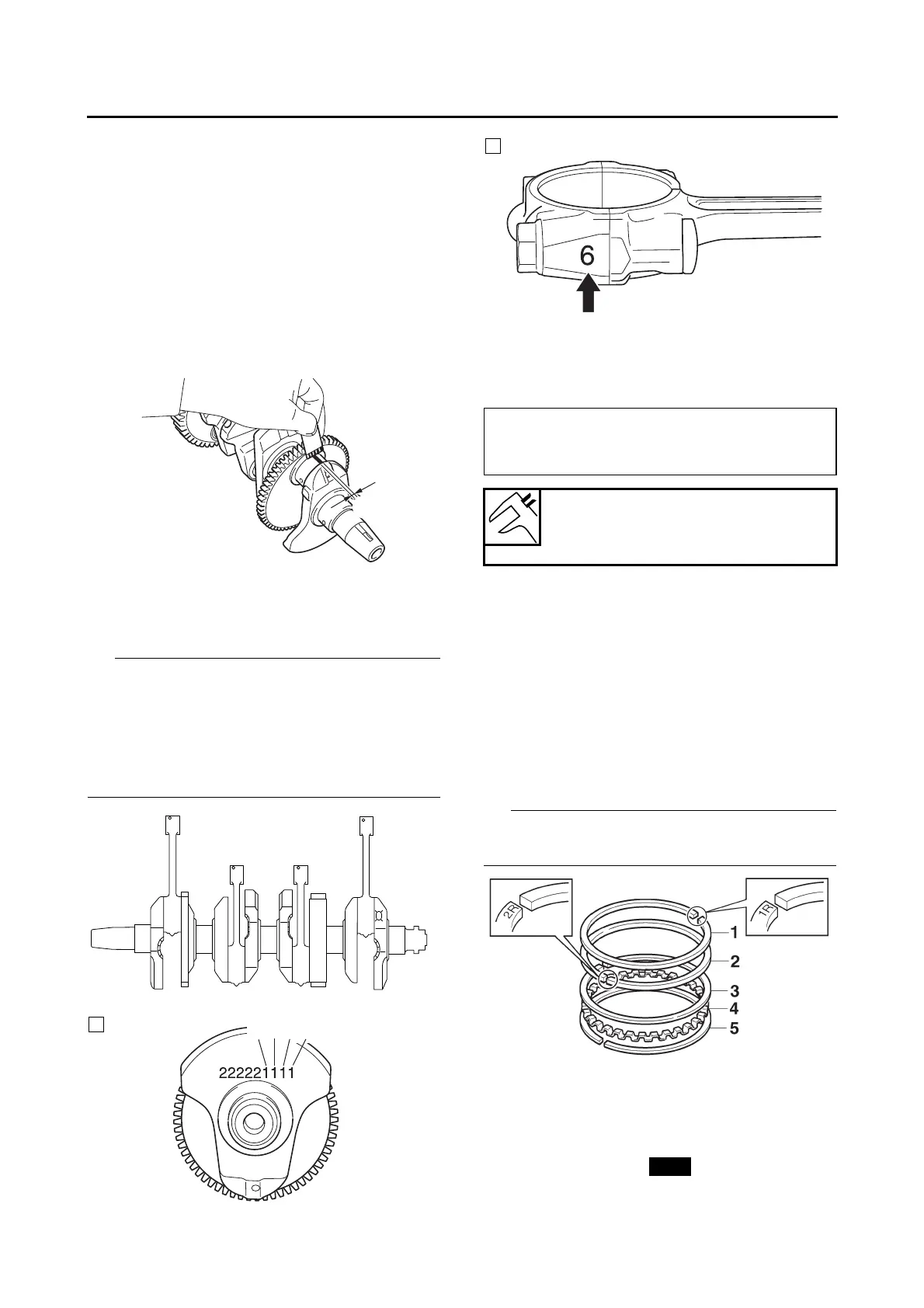
• The numbers “A” stamped into the crankshaft
web and the numbers “B” on the connecting
rods are used to determine the replacement
big end bearing sizes.
•P
1
–P
4
refer to the bearings shown in the crank-
shaft illustration.
For example, if the connecting rod P
1
and the
crankshaft web P
1
numbers are 6 and 1 re-
spectively, then the bearing size for P
1
is:
EAS26170
INSTALLING THE CONNECTING RODS AND
PISTONS
The following procedure applies to all of the pis-
tons and connecting rods.
1. Install:
• Top ring “1”
• 2nd ring “2”
• Upper oil ring rail “3”
• Oil ring expander “4”
• Lower oil ring rail “5”
Be sure to install the piston rings so that the
manufacturer’s marks face up.
2. Install:
• Piston “1”
(onto the respective connecting rod “2”)
• Piston pin “3”
• Piston pin clips “4”
e
P
1
(connecting rod) - P
1
(crankshaft)
=
6 - 1 = 5 (yellow)
Bearing color code
1.Blue 2.Black 3.Brown 4.Green
5.Yellow 6.Pink