CRANKSHAFT
5-95
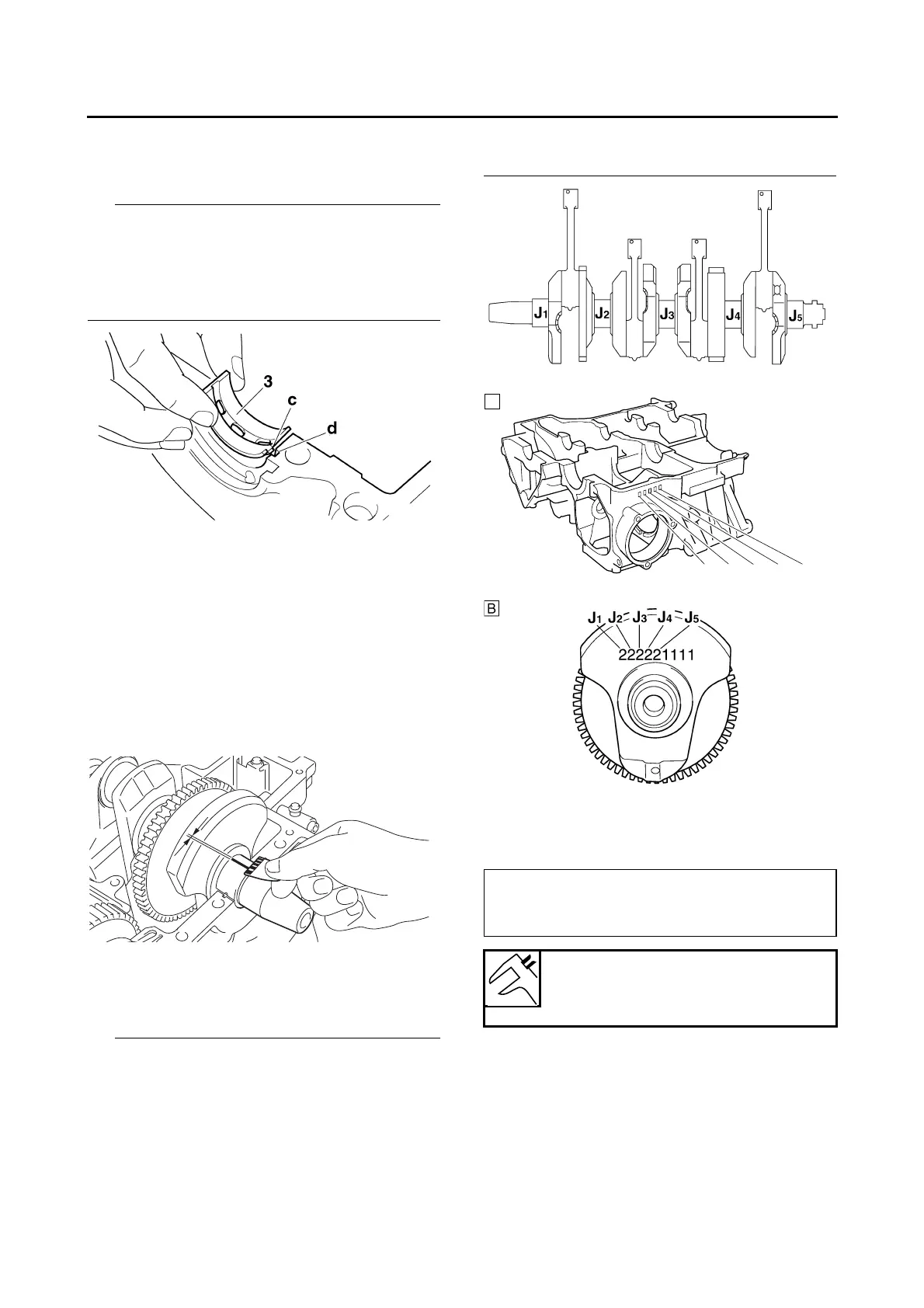
e. Install the crankshaft journal lower bearings
“3” into the lower crankcase and assemble
the crankcase halves.
• Align the projections “c” of the crankshaft jour-
nal lower bearings with the notches “d” in the
lower crankcase.
• Do not move the crankshaft until the clearance
measurement has been completed.
f. Tighten the bolts to specification in the tight-
ening sequence cast on the crankcase.
Refer to “CRANKCASE” on page 5-77.
g. Remove the lower crankcase and the crank-
shaft journal lower bearings.
h. Measure the compressed Plastigauge®
width “e” on each crankshaft journal.
If the crankshaft-journal-to-crankshaft-jour-
nal-bearing clearance is out of specification,
select replacement crankshaft journal bear-
ings.
▲▲▲▲ ▲ ▲▲▲▲▲▲▲▲▲ ▲ ▲▲▲▲ ▲ ▲▲▲▲ ▲ ▲▲▲▲▲▲▲
4. Select:
• Crankshaft journal bearings (J
1
–J
5
)
• The numbers “A” stamped into the lower crank-
case and the numbers “B” stamped into the
crankshaft web are used to determine the re-
placement crankshaft journal bearing sizes.
•J
1
–J
5
refer to the bearings shown in the lower
crankcase and crankshaft web illustration.
• If J
1
–J
5
are the same, use the same size for all
of the bearings.
For example, if the lower crankcase J
1
and
crankshaft web J
1
numbers are 6 and 2 re-
spectively, then the bearing size for J
1
is:
EAS26200
INSTALLING THE CRANKSHAFT
1. Install:
• Crankshaft journal upper bearings
(into the upper crankcase)
• Crankshaft journal lower bearings
(into the lower crankcase)
222221111
J
1
(crankcase) - J
1
(crankshaft web) + 2
=
6 - 2 + 2 = 6 (pink)
Bearing color code
2.Black 3.Brown 4.Green 5.Yel-
low 6.Pink 7.Red 8.White