[A]
[A-4]
[B-1]
[C-3]
[A-1]
[A-2]
[A-3]
[B-3]
[B-2]
•
•
•
•
•
•
•
•
•
•
•
•
•
•
•
•
•
•
•
[C-1]
[C-2]
Comes on
Fails to
come on
Yes
Yes
Yes
No
No
Flashes
Yes
Yes
Cannot delete OK
No
No
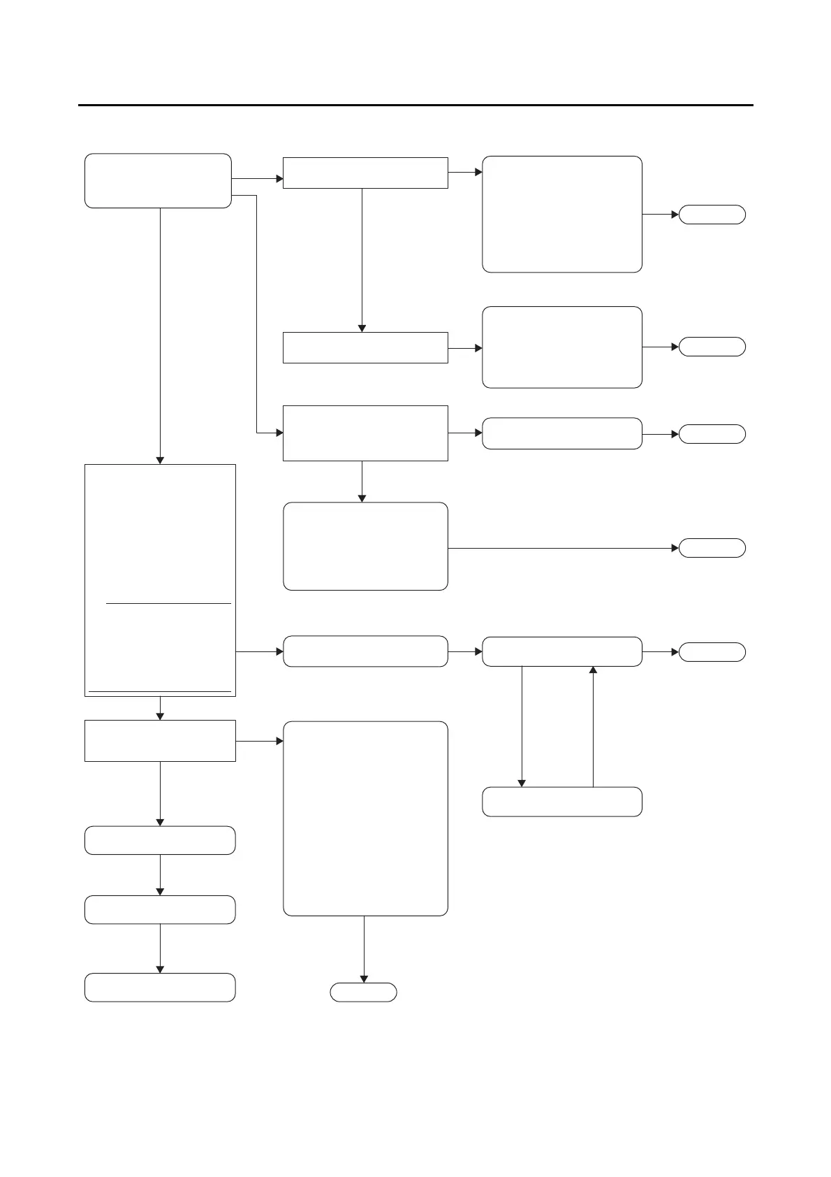
Turn the main switch to
“ON”, and check the ABS
warning light.
The ABS warning light
comes on.
Connect the test coupler
adapter to the ABS test
coupler, and then check for
fault codes in the multi-
function meter right
display.
Are fault codes displayed
in the multi-function meter
right display?
Are fault codes displayed
in the multi-function meter
right display?
Record any fault codes that
are displayed.
If there are any fault codes for
the fuel injection system, those
fault codes will be displayed
first.
Fault code number is
not displayed.
Finished.
Does only the ABS warning
light fail to come on?
Do all indicator lights fail to
come on?
The ABS warning light flashes.
Is the test coupler adapter
connected to the ABS test
coupler?
The T/C terminal (sky blue) of the
ABS test coupler is grounded.
The meter assembly circuit is
defective.
The hydraulic unit assembly is
defective.
Diagnosis using the fault
codes.
The ABS ECU fuse is blown.
The meter assembly circuit is
defective.
The hydraulic unit assembly is
defective.
There is a break in the wire
harness between the ABS ECU
and the meter assembly.
The battery voltage is low.
The ABS ECU coupler is
disconnected or a coupler pin is
pulled out.
The ABS warning light(LED) is
defective.
The wire harness is grounded
between the ABS ECU and the
meter assembly.
The meter assembly circuit is
defective.
The ABS ECU is defective.
(The ABS warning light
flashes every 0.5 second.)
Delete function test.
Delete the fault codes.
The main switch is defective.
The battery voltage is low.
The main fuse is blown.
The meter assembly circuit is
open.
Disconnect the test coupler
adapter.
Final check.
The ABS warning light
remain on.
Return to [A].
Return to [A].
Return to [A].
Return to [A].
Return to [A].
Return to [A].
TIP