ELECTRICAL COMPONENTS
8-188
EAS29100
CHECKING THE ACCELERATOR POSITION
SENSOR
1. Remove:
• Accelerator position sensor
(from the throttle bodies)
EWA1MC1003
• Handle the accelerator position sensor with
special care.
• Never subject the accelerator position sen-
sor to strong shocks. If the accelerator po-
sition sensor is dropped, replace it.
2. Check:
• Accelerator position sensor maximum resis-
tance
Out of specification → Replace the accelera-
tor position sensor.
▼▼▼▼ ▼ ▼▼▼▼▼▼▼▼▼ ▼ ▼▼▼▼ ▼ ▼▼▼▼ ▼ ▼▼▼▼▼▼▼
a. Connect the pocket tester (Ω × 1k) to the ac-
celerator position sensor terminals as shown.
b. Measure the accelerator position sensor
maximum resistance.
▲▲▲▲ ▲ ▲▲▲▲▲▲▲▲▲ ▲ ▲▲▲▲ ▲ ▲▲▲▲ ▲ ▲▲▲▲▲▲▲
3. Install:
• Accelerator position sensor
When installing the accelerator position sensor,
adjust its angle properly. Refer to “ADJUSTING
THE ACCELERATOR POSITION SENSOR” on
page 7-11.
EAS1MC1083
CHECKING THE THROTTLE SERVO MOTOR
1. Remove:
• Air filter case
Refer to “GENERAL CHASSIS” on page 4-1.
2. Check:
• Throttle valve operation
Throttle valves do not fully close → Replace
the throttle bodies.
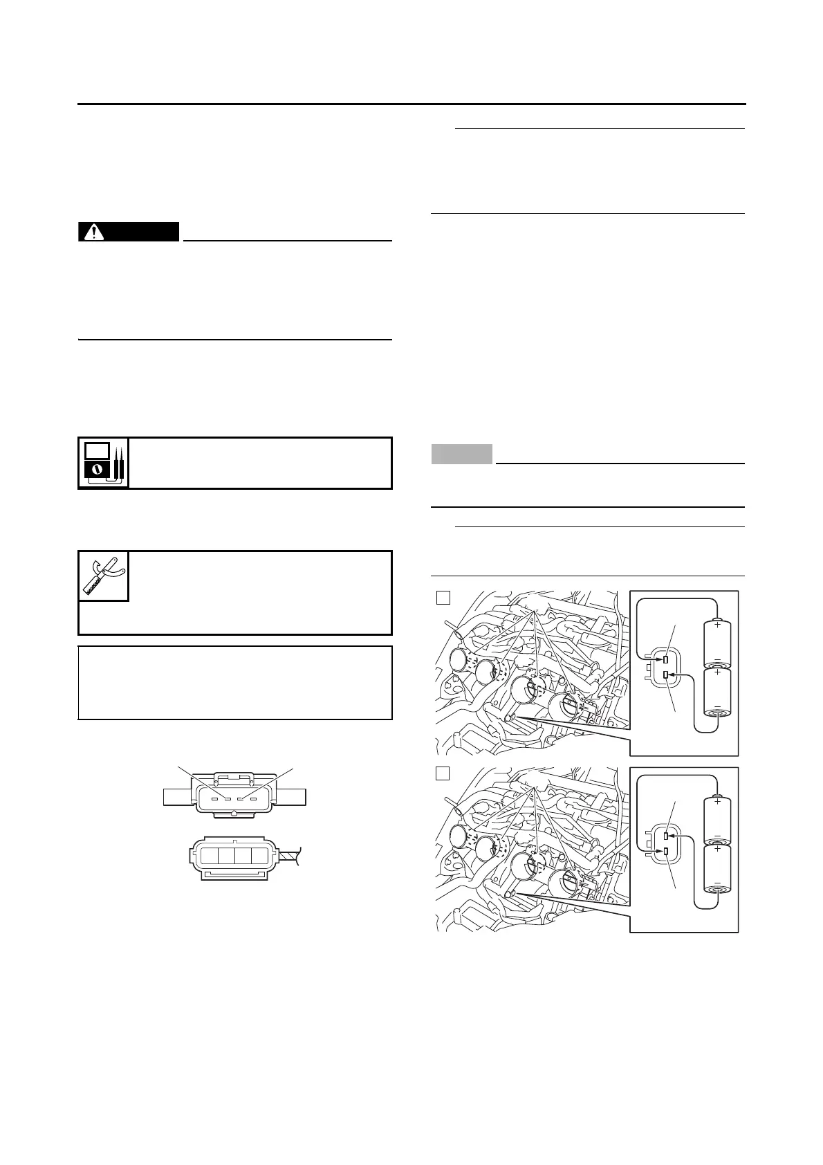
▼▼▼▼ ▼ ▼▼▼▼▼▼▼▼▼ ▼ ▼▼▼▼ ▼ ▼▼▼▼ ▼ ▼▼▼▼ ▼▼▼
a. Connect two C-size batteries to the throttle
servo motor terminals “1” as shown.
ECA1MC1004
Do not use a 12 V battery to operate the throt-
tle servo motor.
Do not use old batteries to operate the throttle
servo motor.
▲▲▲▲ ▲ ▲▲▲▲▲▲▲▲▲ ▲ ▲▲▲▲ ▲ ▲▲▲▲ ▲ ▲▲▲▲ ▲▲▲
Resistance
1.08–2.52 kΩ
Pocket tester
90890-03112
Analog pocket tester
YU-03112-C
• Positive tester probe →
blue “1”
• Negative tester probe →
black/blue “2”
A. Check that the throttle valves “2” open.
B. Check that the throttle valves “2” fully close.
1
1
3V
2
A
1
1
3V
2
B