2.1 Ratings and Specifications
2.1.4 Specifications
2-8
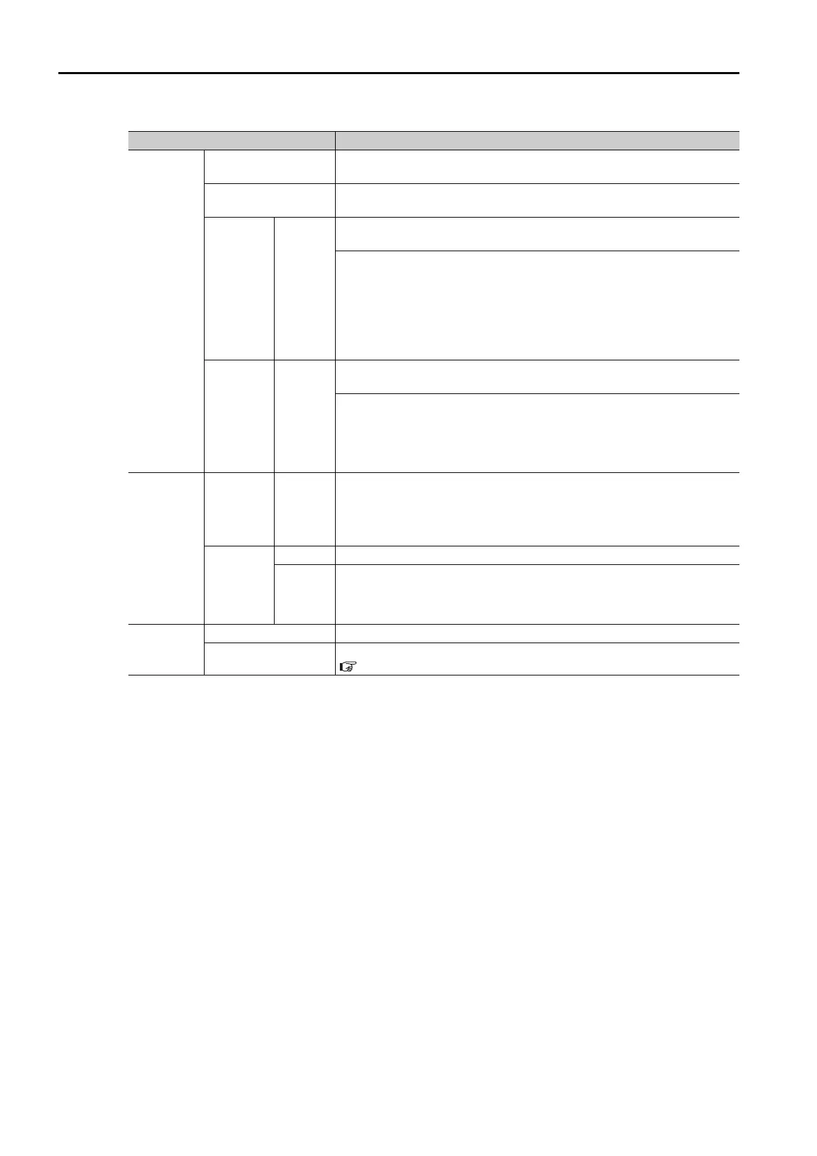
I/O Signals
Encoder Divided
Pulse Output
Phase A, phase B, phase C: Line-driver output
Number of divided output pulses: Any setting is allowed.
Overheat Protection
Input
Number of input points: 1
Input voltage range: 0 V to +5 V
Sequence
Input
Signals
Fixed
Inputs
Allowable voltage range: 24 VDC ±20%
Number of input points: 4
Input method: Sink inputs or source inputs
Input Signals
• CCW-OT (CCW Drive Prohibit Input) signal
• CW-OT (CW Drive Prohibit Input) signal
• /HOME (Origin Signal Input) signal
• EXSTOP (External Stop Input) signal
Positive or negative logic can be changed in the parameters.
Sequence
Output
Signals
Fixed
Output
Allowable voltage range: 5 VDC to 30 VDC
Number of output points: 4
Output Signals
• ALM (Servo Alarm Output) signal
• /WARN (Warning Signal Output) signal
• /BK (Brake) signal
• /S-RDY (Servo Ready Output) signal
Communi-
cations
Digital
Operator
Communi-
cations
(CN3)
Inter-
faces
Digital Operator (JUSP-OP05A-1-E)
USB Com-
munica-
tions
(CN7)
Interface Personal computer (with SigmaWin+)
Commu-
nica-
tions
Standard
Conforms to USB2.0 standard (12 Mbps).
Displays/
Indicators
SERVOPACK CHARGE and PWR indicators, and one-digit seven-segment display
DeviceNet Module
Refer to the following section for details.
1.5.2 LED Indicators on page 1-9
Continued on next page.
Continued from previous page.
Item Specification
 Loading...


