5.2 b: Application
112 YASKAWA ELECTRIC SIEP C710616 30B YASKAWA AC Drive T1000A Technical Manual
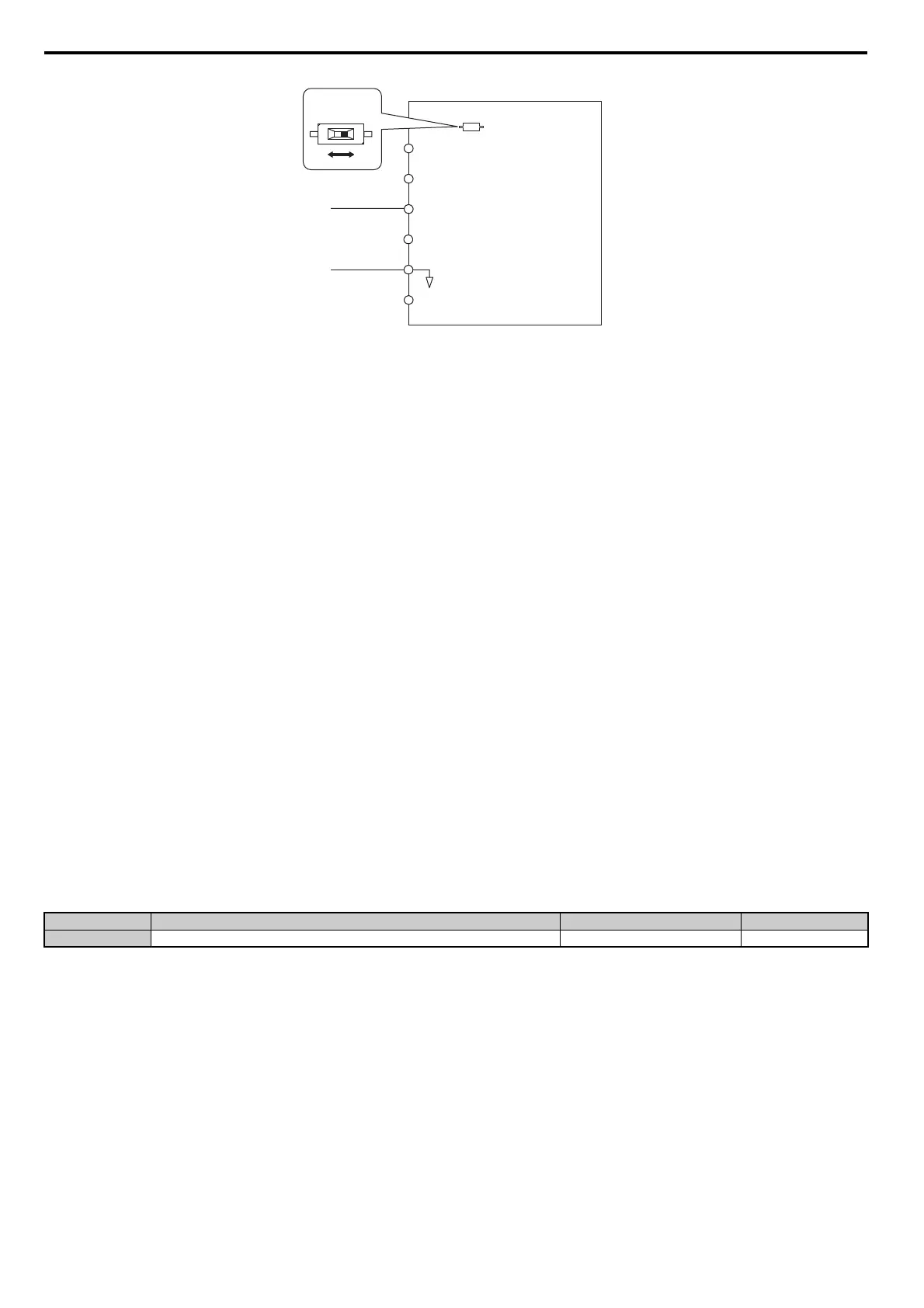
Figure 5.2
Figure 5.2 Setting the Frequency Reference as a Current Signal to Terminal A2
DIP switch S1 must first be set for current input.
Switching between Main/Auxiliary Frequency References
The frequency reference input can be switched between the analog terminals A1, A2, and A3 using multi-speed inputs.
Refer to Multi-Step Speed Selection on page 155 for details on using this function.
Setting 2: MEMOBUS/Modbus Communications
This setting requires that the frequency reference is entered via the RS-485/422 serial communications port (control
terminals R+, R-, S+, S-). For instructions, see MEMOBUS/Modbus Communications on page 445.
Setting 3: Option card
This setting requires that the frequency reference is entered via an option board plugged into connector CN5-A on the
drives control board. Consult the manual supplied with the option board for instructions on integrating the drive with the
communication system.
Note: If the frequency reference source is set for an option PCB (b1-01 = 3), but an option board is not installed, an OPE05 Operator
Programming Error will be displayed on the digital operator and the drive will not run.
Setting 4: Pulse Train Input
If b1-01 is set to 4, the frequency reference must be provided by a pulse train signal to terminal RP. Follow the directions
below to make sure the pulse signal is working properly.
Verifying Pulse Train is Working Properly
• Make sure that b1-01 is set to 4 and H6-01 is set to 0.
• Set the pulse input scaling H6-02 to the pulse train frequency value that equals 100% of the frequency reference.
• Enter a pulse train signal to terminal RP and check if the correct frequency reference is displayed.
n
b1-02: Run Command Source 1
Parameter b1-02 determines the Run command source 1 in the REMOTE mode.
Setting 0: Operator
When the b1-02 = 0, the LO/RE light will switch on and the RUN key will enter a Run command to start the drive.
Setting 1: Control Circuit Terminal
This setting requires that the Run and Stop commands are entered from the digital input terminals. The following
sequences can be used:
• 2-wire sequence 1:
Two inputs (FWD/Stop-REV/Stop). Initializing the drive by setting A1-03 = 2220, presets the terminals S1 and S2 to
these functions. This is the default setting of the drive. Also refer to Setting 40, 41: Forward run, Reverse run
command for 2-wire sequence on page 187.
• 2-wire sequence 2:
Two inputs (Start/Stop-FWD/REV). Also refer to Setting 42, 43: Run and direction command for 2-wire sequence 2
No. Parameter Name Setting Range Default
b1-02 Run Command Source 1 0 to 3 1
Drive
A1 Analog Input 1
0 or 4 to 20 mA
AC Analog input common
+V
-V
10.5 V, 20 mA power supply
-10.5 V, 20 mA power supply
A2 Analog Input 2
A3 Analog Input 3
DIP switch S1
VI