3.8 Control Circuit Wiring
YASKAWA ELECTRIC SIEP C710616 30B YASKAWA AC Drive T1000A Technical Manual 61
Electrical Installation
3
n Output Terminals
Table 3.7 lists the output terminals on the drive. Text in parenthesis indicates the default setting for each multi-function
output.
Table 3.7 Control Circuit Output Terminals
n Serial Communication Terminals
Table 3.8 Control Circuit Terminals: Serial Communications
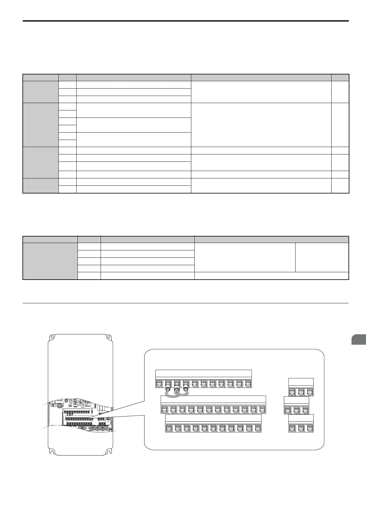
u Terminal Configuration
Control circuit terminals should are arranged as shown in Figure 3.17.
Figure 3.22
Figure 3.17 Control Circuit Terminal Arrangement
Type
<1> Refrain from assigning functions to digital outputs that involve frequent switching, as doing so may shorten relay performance life. Switching
life is estimated at 200,000 times (assumes 1 A, resistive load).
No. Terminal Name (Function) Function (Signal Level) Default Setting Page
Fault Relay
MA
N.O.
30 Vdc, 10 mA to 1 A; 250 Vac, 10 mA to 1 A
Minimum load: 5 Vdc, 10 mA
190
MB
N.C. output
MC
Fault output common
Multi-Function
Digital Output
<1>
M1
Multi-function digital output (During run)
30 Vdc, 10 mA to 1 A; 250 Vac, 10 mA to 1 A
Minimum load: 5 Vdc, 10 mA
190
M2
M3
Multi-function digital output (Zero Speed)
M4
M5
Multi-function digital output (Speed Agree 1)
M6
Monitor Output
MP
Pulse train output (Output frequency) 32 kHz (max) 208
FM
Analog monitor output 1 (Output frequency)
-10 to +10 Vdc, 0 to +10 Vdc, or 4-20 mA
Use jumper S5 on the terminal board to select between voltage or current output
signals.
207
AM
Analog monitor output 2 (Output current)
AC
Monitor common 0 V –
Safety Monitor
Output
DM+
Safety monitor output
Outputs status of Safe Disable function. Closed when both Safe Disable
channels are closed. Up to +48 Vdc 50 mA
476
DM-
Safety monitor output common
Type
<1> Enable the termination resistor in the last drive in a MEMOBUS network by setting DIP switch S2 to the ON position. For more information on
the termination resistor, see Control I/O Connections on page 65.
No. Signal Name Function (Signal Level)
MEMOBUS/Modbus
Communication
<1>
R+
Communications input (+)
MEMOBUS/Modbus communication: Use a RS-485 or
RS-422 cable to connect the drive.
RS-485/422
MEMOBUS/Modbus
communication protocol
115.2 kbps (max.)
R-
Communications input (-)
S+
Communications output (+)
S-
Communications output (-)
IG
Shield ground 0 V
E(G)
HC H1 H2 DM+ DM- IG R+ R- S+ S-
S1 S2 S3 S4 S5 S6 S7 S8 SN SC SP
V+ AC V- A1 A2 A3 FM AM AC MP RP AC
MA MB MC
M1 M2 M5
M3 M6 M4
E(G)
HC H1 H2 DM+ DM- IG R+ R- S+ S-
S1 S2 S3 S4 S5 S6 S7 S8 SN SC SP
V+ AC V- A1 A2 A3 FM AM AC MP RP AC
YEG

 Loading...


