3.9 Control I/O Connections
66 YASKAWA ELECTRIC SIEP C710616 30B YASKAWA AC Drive T1000A Technical Manual
u Using the Pulse Train Output
The pulse train output terminal MP can either supply power but can also be used with external power supply. Peripheral
devices should be connected in accordance with the specifications listed below. Failure to do so can cause unexpected
drive operation, and can damage the drive or connected circuits.
n
Using Power from the Pulse Output Terminal (Source Mode)
The high voltage level of the pulse output terminal depends on the load impedance.
Note: The load resistance needed in order to get a certain high level voltage V
MP
can be calculated by:
Figure 3.28
Figure 3.23 Pulse Output Connection Using Internal Voltage Supply
n Using External Power Supply (Sink Mode)
The high voltage level of the pulse output signal depends on the external voltage applied. The voltage must be between
12 and 15 Vdc. The load resistance must be adjusted so that the current is lower than 16 mA.
Figure 3.29
Figure 3.24 Pulse Output Connection Using External Voltage Supply
u Terminal A2 Input Signal Selection
Terminal A2 can be used to input either a voltage or a current signal. Select the signal type using switch S1 as explained
in Table 3.13. Set parameter H3-09 accordingly as shown in Table 3.14. Refer to Switches and Jumpers on the Terminal
Board on page 64 for locating switch S1.
Note: If terminals A1 and A2 are both set for frequency bias (H3-02 = 0 and H3-10 = 0), both input values will be combined to create
the frequency reference.
Sourcing Mode
Load Impedance R
L
(kΩ) Output Voltage V
MP
(V) (insulated)
1.5 kΩ 5 V
4 kΩ 8 V
10 kΩ 10 V
External Power Supply (V) Load Impedance (kΩ)
12 to 15 Vdc ±10% 1.0 kΩ or higher
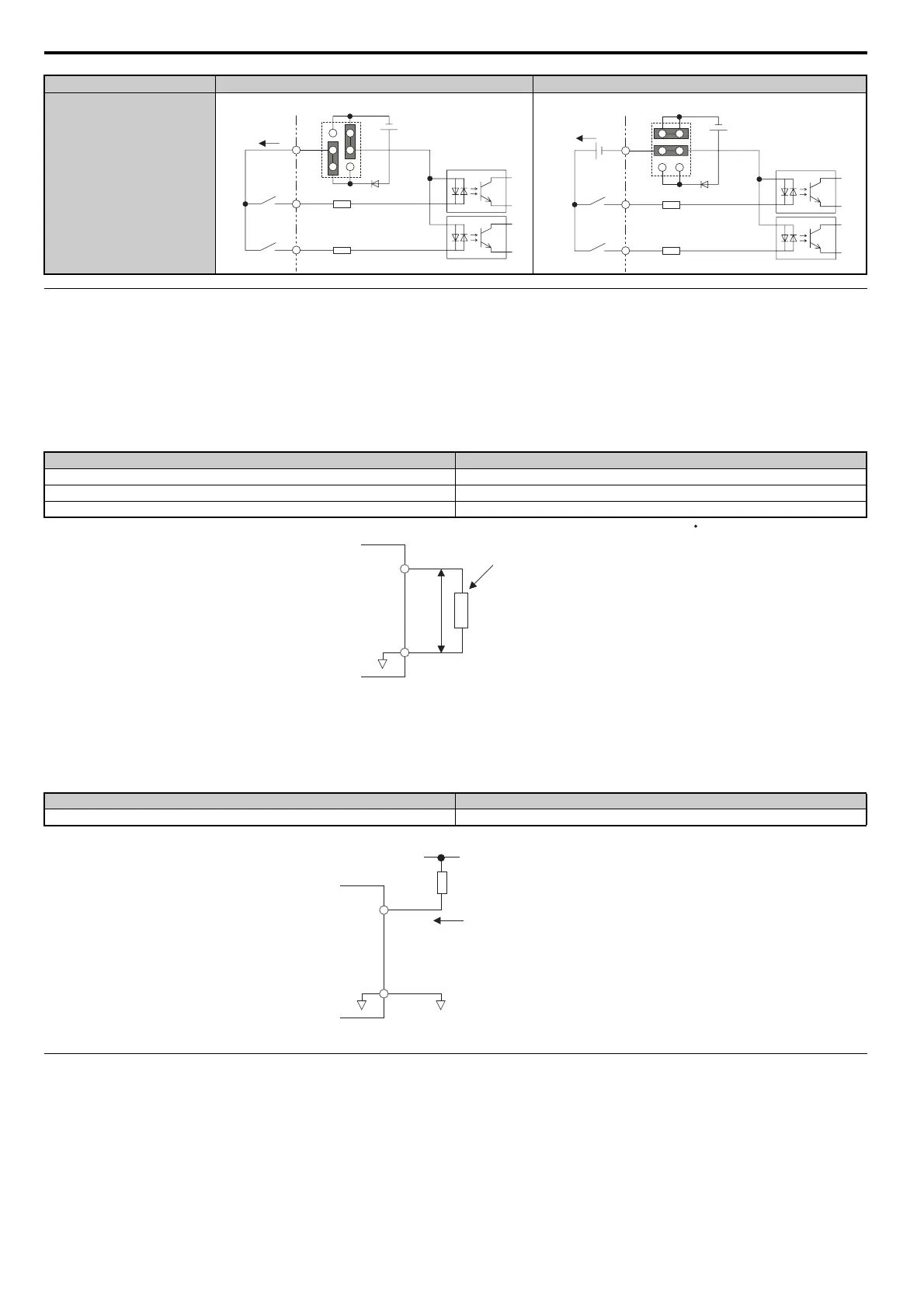
Drive Internal Power Supply External 24 Vdc Power Supply
24 Vdc
H1
H2
HC
Jumper S3
24 Vdc
H1
H2
HC
External
24 Vdc
Jumper S3
R
L
= V
MP
2 / (12 - V
MP
)
MP
AC
V
MP
R
L
Load Impedance
MP
AC
Load Impedance
Sink Current
External Power Supply