46 YASKAWA ELECTRIC SIEP C710616 30B YASKAWA AC Drive T1000A Technical Manual
3.2 Standard Connection Diagram
3.2 Standard Connection Diagram
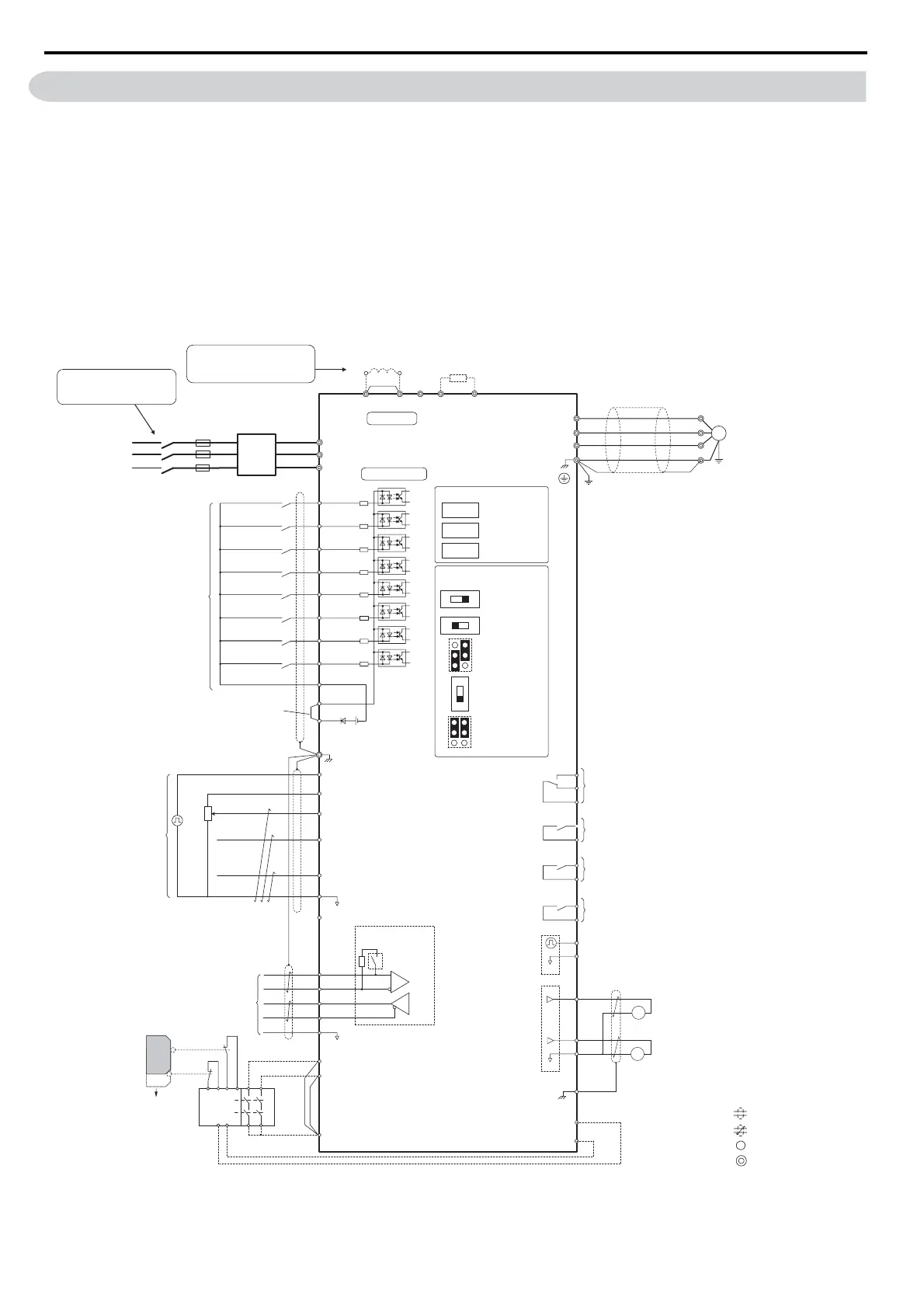
Connect the drive and peripheral devices as shown in Figure 3.1. It is possible to set and run the drive via the digital
operator without connecting digital I/O wiring. This section does not discuss drive operation; Refer to Start-Up
Programming & Operation on page 71 for instructions on operating the drive.
NOTICE: Inadequate wiring could result in damage to the drive. Install adequate branch circuit short circuit protection per applicable
codes. The drive is suitable for circuits capable of delivering not more than 100,000 RMS symmetrical amperes, 240 Vac maximum
(200 V Class) and 480 Vac maximum (400 V Class).
NOTICE: When the input voltage is 440 V or higher or the wiring distance is greater than 100 meters, pay special attention to the
motor insulation voltage or use a drive duty motor. Failure to comply could lead to motor insulation breakdown.
NOTICE: Do not connect AC control circuit ground to drive enclosure. Improper drive grounding can cause control circuit malfunction.
NOTICE: The minimum load for the relay outputs M1-M2, M3-M4, M5-M6, and MA-MB-MC is 10 mA.
Figure 3.1
Figure 3.1 Drive Standard Connection Diagram (example: CIMR-T2A0040)
+
−
+
+
++
M
U/T
1
V/T2
W/T
U
V
W
3
Ground
Terminals -, +1, +2, B1, B2 are
for connection options. Never
connect power supply lines to
these terminals
DC reactor
(option)
UX
+
−
+
+
++
+
−
UX
S
1
S2
S3
S4
S5
S6
S7
MP
DM
DM
RP
A
1
A2
A3
0
V
AC
R
R
S
S
IG
H
1
H2
HC
Drive
B112
B2
2
kΩ
S8
SC
0 V
0 V
AC
FM
AM
AC
E (G)
S
1
S2
<1>
<2>
<3>
<11>
<7>
<12>
<13>
<13>
<8>
<10>
<7>
<5>
<4>
−
+24 V
+V
MA
M
1
M2
MB
MC
Jumper
Braking resistor
(option)
Forward Run / Stop
Reverse Run / Stop
External fault
Fault reset
Multi-speed step 1
Multi-speed step 2
Baseblock
Jog speed
Multi-function
digtial inputs
(default setting)
Sink / Source mode
selection wire link
(default: Sink)
CN5-C
CN5-B
CN5-A
Option board connectors
Pulse Train Input (max 32 kHz)
Shield ground terminal
Multi-function
analog/ pulse
train inputs
Power supply +10.5 Vdc, max. 20 mA
Analog Input 1 (Frequency Reference Bias)
-10 to +10 Vdc (20 k
Ω
)
Analog Input 2 (Frequency Reference Bias)
-10 to +10 Vdc (20 k
Ω
)
0 or 4 to 20 mA (250
Ω
)
Analog Input 3 / PTC Input (Aux. frequency
reference)
-10 to +10 Vdc (20 k
Ω
)
−V
Power supply, -10.5 Vdc, max. 20 mA
Safety
switch
MEMOBUS/Modbus
comm. RS485/422
max. 115.2 kBps
Safe Disable inputs
Wire
jumper
Open
Safety relay /
controller
Termination resistor
(120
Ω
, 1/2 W)
DIP
Switch S2
Fault relay output
250 Vac, max. 1 A
30 Vdc, max 1 A
(min. 5 Vdc, 10 mA)
Multi-function relay output (During Run)
250 Vac, max. 1 A
30 Vdc, max 1 A
(min. 5 Vdc, 10 mA)
Multi-function pulse train output
(Output frequency)
0 to 32 kHz (2.2 k
Ω
)
Multi-function analog output 1
(Output frequency)
-10 to +10 Vdc (2mA) or 4 to 20 mA
Multi-function analog output 2
(Output current)
-10 to +10 Vdc (2mA) or 4 to 20 mA
EDM (Safety Electronic Device Monitor)
Main Circuit
Control Circuit
shielded line
twisted-pair shielded line
main circuit terminal
control circuit terminal
R/L1
S/L2
T/L3
Three-phase
power supply
200 to 240 V
50/60 Hz
R
S
T
Main
Switch
Fuse
EMC
Filter
Motor
Shielded
Cable
M3
M4
Multi-function relay output (Zero Speed)
250 Vac, max. 1 A
30 Vdc, max 1 A
(min. 5 Vdc, 10 mA)
M5
M6
Multi-function relay output (Speed Agree 1)
250 Vac, max. 1 A
30 Vdc, max 1 A
(min. 5 Vdc, 10 mA)
SP
SN
<9>
AMFM
V
I
V
I
DIP Switch S1
A2 Volt/Curr. Sel
DIP Switch S4
A3 Analog/PTC
Input Sel
PTC
AI
Off
On
DIP Switch S2
Term. Res. On/Off
Jumper S3
H1, H2
Sink/Source Sel.
Jumper S5
AM/FM Volt./Curr.
Selection
Terminal board
jumpers and switches
FM
+
−
AM
<6>
<14>
Wiring sequence should shut off
power to the drive when a fault
output is triggered.
<15>
YEG