4.3 The Drive and Programming Modes
80 YASKAWA ELECTRIC SIEP C710616 30B YASKAWA AC Drive T1000A Technical Manual
The following example is a continuation of the steps above. Here, parameter C1-02 is accessed using the Verify Menu,
and is changed again from 10.0 s to 20.0 s.
To check the list of edited parameters:
u Simplified Setup Using the Setup Group
In the Setup Group, the drive lists the basic parameters needed to set up the drive for the application. It provides a
simplified way to get the application running right away by showing only the most important parameters.
n
Using the Setup Group
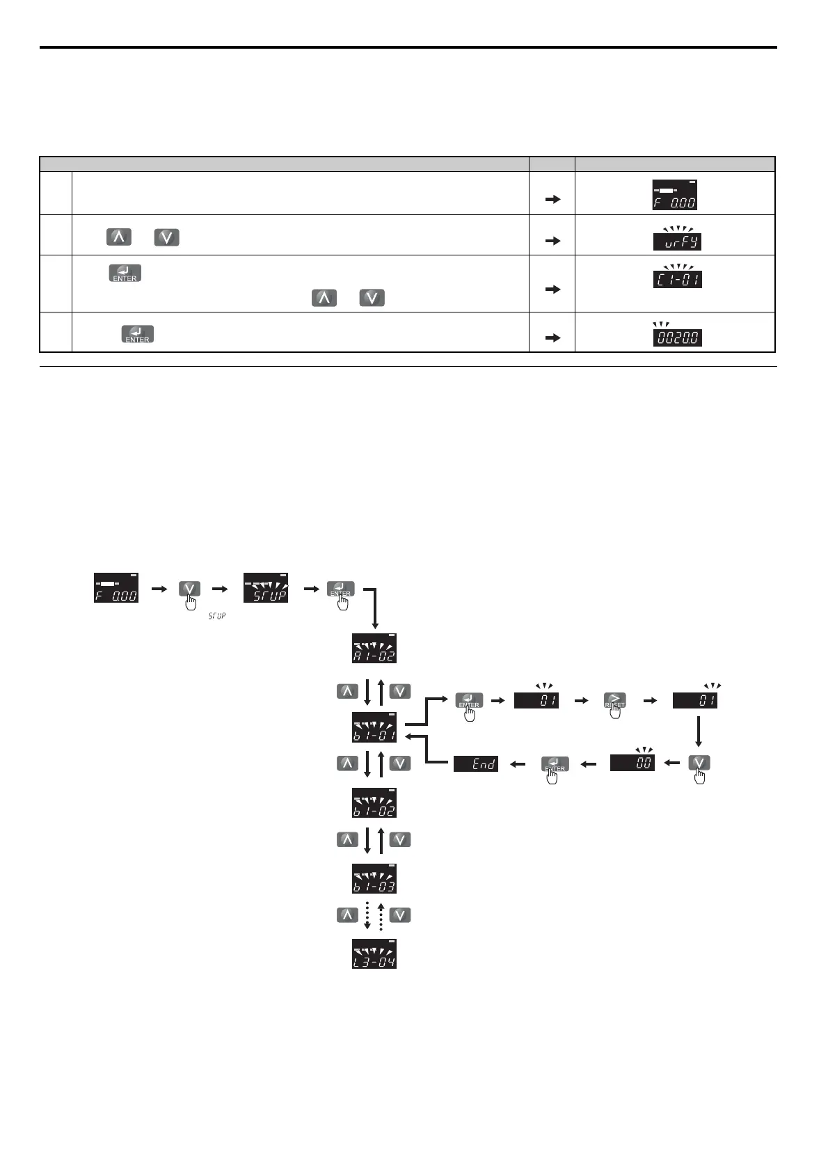
Figure 4.6 illustrates how to enter and how to change parameters in the Setup Group.
In this example, the Setup Group is accessed to change b1-01 from 1 to 0. This changes the source of the frequency
reference from the control circuit terminals to the digital operator.
Figure 4.6
Figure 4.6 Setup Group Example
Step Display/Result
1. Turn on the power to the drive. The initial display appears.
2.
Press or until the display shows the top of the Verify Menu.
3.
Press to enter the list of parameters that have been edited from their original default settings.
If parameters other than C1-02 have been changed, use the or key to scroll until C1-02 appears.
4.
Press the key to access the setting value. Left digit flashes.
<1> Use the up and down arrow keys to scroll through the Setup Group. Press the ENTER key to view or change parameter settings.
<2> To return to the previous menu without saving changes, press the ESC key.
ALM
DIGITAL OPERATOR JVOP-182
REV DRV FOUT
DRV
ALM
DIGITAL OPERATOR JVOP-182
REV DRV FOUT
ALM
DIGITAL OPERATOR JVOP-182
REV DRV FOUT
ALM
DIGITAL OPERATOR JVOP-182
REV DRV FOUT
ALM
DIGITAL OPERATOR JVOP-182
REV DRV FOUT
ALM
DIGITAL OPERATOR JVOP-182
REV DRV FOUT
ALM
DIGITAL OPERATOR JVOP-182
REV DRV FOUT
ALM
DIGITAL OPERATOR JVOP-182
REV DRV FOUT
DRV
Control Circuit
Terminal
Parameter Display
Select digit to edit
Operator
<1>
<2>
Press until
appears
<2>
<2>
Frequency reference
appears when
powered up