86 YASKAWA ELECTRIC SIEP C710616 30B YASKAWA AC Drive T1000A Technical Manual
4.5 Powering Up the Drive
4.5 Powering Up the Drive
u Powering Up the Drive and Operation Status Display
n Powering Up the Drive
Review the following checklist before turning the power on.
n
Status Display
When the power supply to the drive is turned on, the digital operator lights will appear as follows:
Item to Check Description
Power supply voltage
Ensure the power supply voltage is correct:
200 V class: 3-phase 200 to 240 Vac 50/60 Hz
400 V class: 3-phase 380 to 480 Vac 50/60 Hz
Properly wire the power supply input terminals (R/L1, S/L2, T/L3).
Check for proper grounding of drive and motor.
Drive output terminals and motor
terminals
Properly wire drive output terminals U/T1, V/T2, and W/T3 with motor terminals U, V, and W.
Control circuit terminals Check control circuit terminal connections.
Drive control terminal status Open all control circuit terminals (off).
Status of the load and connected
machinery
Decouple the motor from the load.
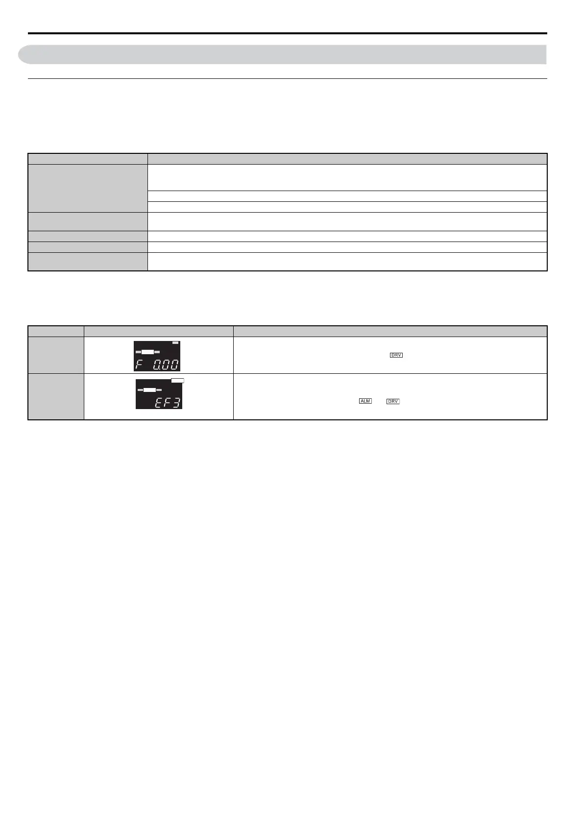
No. Name Description
Normal Operation
The data display area displays the frequency reference. is lit.
Fault
External fault (example)
Data displayed varies by the type of fault. Refer to Fault Displays, Causes, and Possible Solutions on page 277
for more information and possible solution. and are lit.
ALM
DIGITAL OPERATOR JVOP-182
REV DRV FOUT
DRV
ALM
DIGITAL OPERATOR JVOP-182
REV DRV FOUT
DRV
ALM