8.3 Connecting Peripheral Devices
YASKAWA ELECTRIC SIEP C710616 30B YASKAWA AC Drive T1000A Technical Manual 339
Peripheral Devices &
Options
8
8.3 Connecting Peripheral Devices
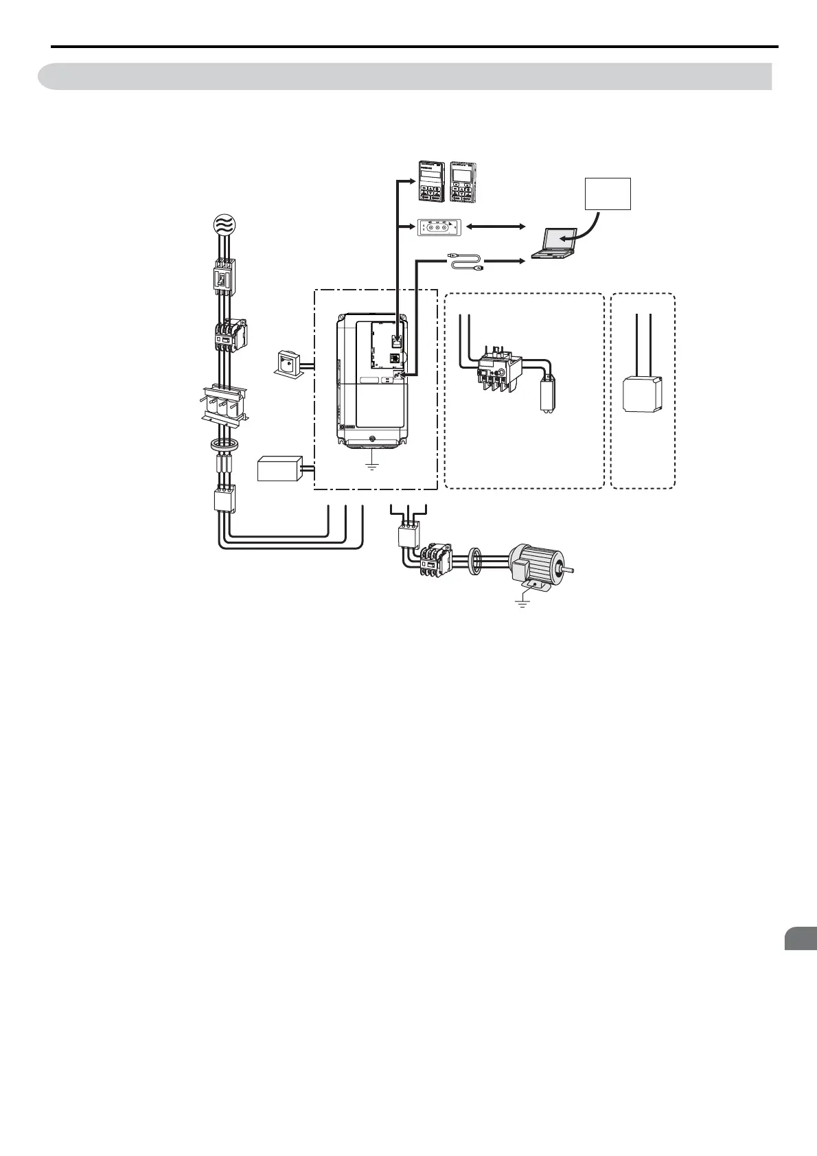
Figure 8.1 illustrates how to configure the drive and motor to operate with various peripheral devices.
• For more detailed instructions on how to install each device shown below, refer to the specific manual for that device.
Figure 8.1
Figure 8.1 Connecting Peripheral Devices
<1> Terminals +1 and +2 for connecting a DC choke are available only in units CIMR-T2A0004 to 0081 and CIMR-
T4A0002 to 0044. Drives above have built in DC chokes.
<2> Terminals B1 and B2 for connecting a braking resistor are available only in units CIMR-T2A0004 to 0138 and
CIMR-T4A0002 to 0072.
<3> When using an external braking chopper in drives from CIMR-T2A0004 to 0138 and CIMR-T4A0002 to 0072
connect the chopper to drive terminals B1 and -. When using larger drives connect the chopper to terminals +3 and -.
C
op
y
V
er
ify
R
e
ad
LOCK
YASKAWA
JVOP-181
USB Copy Unit
COM ERR
PC
DriveWizard
Engineering Software Tools
Power
Supply
Line
Breaker
(MCCB)
and/or
Leakage
Breaker
Magnetic
Contactor
(MC)
DC Reactor
C Reactor
Zero-phase
Reactor
Fuse
Input Side
Noise Filter
Magnetic
Contactor
(switches to
line power)
Zero-phase
Reactor
Thermal Relay
Braking Resistor
or
Braking Resistor Unit
Output Side
Noise Filter
Drive
Ground
24 V control
power supply
unit
B1 B2
Motor
U/T1V/T2W/T3R/L1 S/L2
+2
+1
T/L3
Ground
USB Copy unit
USB Cable
(Type-AB, sold separately)
LED Operator/LCD Operator
USB Cable
(Type-AB)
Braking Unit
−
+3(B1)
<1>
<3>
<2>
YEG