5.8 L: Protection Functions
228 YASKAWA ELECTRIC SIEP C710616 30B YASKAWA AC Drive T1000A Technical Manual
u L7: Torque Limit
The torque limit function can be used to limit the torque in each of the four quadrants individually and thereby protect the
machinery. It can be used in OLV, CLV, AOLV/PM, and CLV/PM control modes. The limit can be either set by
parameters or by analog inputs. A digital output programmed for “During torque limit” (H2-01, H2-02, H2-03 = 30) can
be switched when the drive is operating at the torque limit.
n
Setting Torque Limits
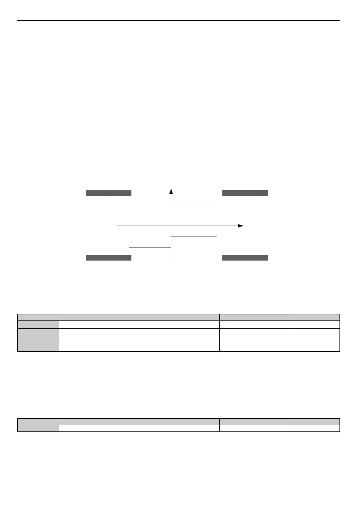
The torque limits are defined by parameters L7-01 to L7-04 for each of the four operation quadrants. Analog inputs can
also be used to either define a general limit for all operation conditions (H3-02, H3-06, H3-10 = 15) or for setting
separate limits for each operation condition (H3-02, H3-06, H3-10 = 10, 11, or 12). Figure 5.88 shows which of the limit
settings is applied in each quadrant.
If two limit values are defined for the same operation conditions, the drive will use the lower value.
Note: The maximum output torque is ultimately limited by the drive output current (max. 150% of drive rated current in HD, 120% in
ND). Output torque will not exceed the limit set for the drive rated current, even if the torque limits are set to higher values.
Example: If parameter L7-01 = 130%, L7-02 to L7-04 = 200%, and a general torque limit of 150% is set by an analog
input (H2-02, H2-06, H2-10 = 15), then the torque limit in quadrant 1 will be 130%, but 150% in all other quadrants.
Figure 5.88
Figure 5.88 Torque Limit Parameters and Analog Input Settings
n L7-01 to L7-04: Torque Limits
These parameters set the torque limits in each operation mode. The value is set as a percentage of the motor rated torque.
Note: If the multi-function analog input (H3-02, H3-06, or H3-10) is programmed for “10: Forward torque limit”, “11: Reverse torque
limit”, “12: Regenerative torque limit”, or “15: General torque limit”, the drive uses the lower value in L7-01 through L7-04, or
analog input torque limit.
n L7-06: Torque Limit Integral Time Constant
Sets the integral time constant for the torque limit function. Decrease this setting for faster torque limit response. Increase
it if oscillation occur when operating at the torque limit.
n
L7-07: Torque Limit Control Method Selection during Accel/Decel
Selects the function of torque limit during acceleration and deceleration.
No. Name Setting Range Default
L7-01
Forward Torque Limit
0 to 300% 200%
L7-02
Reverse Torque Limit
0 to 300% 200%
L7-03
Forward Regenerative Torque Limit
0 to 300% 200%
L7-04
Reverse Regenerative Torque Limit
0 to 300% 200%
No. Name Setting Range Default
L7-06 Torque Limit Integral Time Constant 5 to 10000 ms 200 ms
positive torque
negative torque
10: Positive Torque Limit
12: Regenerative Torque Limit
15: Torque Limit
Parameter L7-04
REV motor rotation
11: Negative Torque Limit
15: Torque Limit
Parameter L7-02
10: Positive Torque Limit
15: Torque Limit
Parameter L7-01
FWD motor rotation
11: Negative Torque Limit
12: Regenerative Torque Limit
15: Torque Limit
Parameter L7-03
quadrant 2
quadrant 3
quadrant 1
quadrant 4
REV run regenerative
REV run motoring
FWD run motoring
FWD run regenerative