48 YASKAWA ELECTRIC SIEP C710616 30B YASKAWA AC Drive T1000A Technical Manual
3.3 Main Circuit Configurations
3.3 Main Circuit Configurations
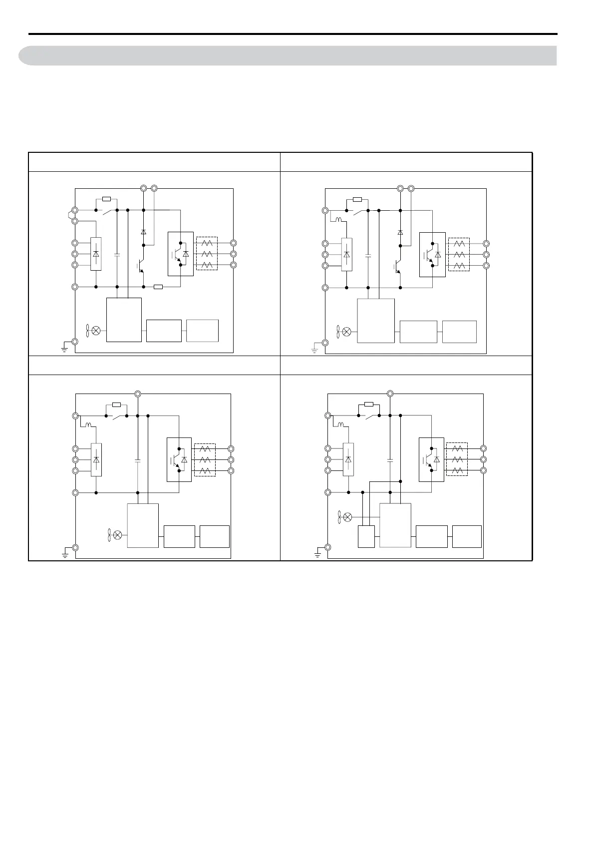
Refer to the Table 3.1 when wiring the drive’s main circuit. Connections may vary based on drive capacity. The DC
power supply for the main circuit also provides power to the control circuit.
NOTICE: Do not use the negative DC bus terminal “-” as a ground terminal. This terminal is at high DC voltage potential. Improper
wiring connections could damage the drive.
Table 3.1 Drive main circuit configurations
CIMR-T2A0004 to 2A0081
CIMR-T4A0002 to 4A0044
CIMR-T2A0110, 2A0138
CIMR-T4A0058, 4A0072
Figure 3.2 Figure 3.4
CIMR-T2A0169, 2A0211
CIMR-T4A0088 to 4A0139
CIMR-T2A0250 to 2A0415
CIMR-T4A0165 to 4A0362
Figure 3.3 Figure 3.5
+1
+2
–
R/L1
S/L2
T/L3
Relay
Gate board
Control
board
Operator
+
Jumper
Current
sensor
U/T1
V/T2
W/T3
B1 B2
+1
–
R/L1
S/L2
T/L3
U/T1
V/T2
W/T3
B1 B2
DC
reactor
+
Relay
Gate board
Control
board
Operator
Current
sensor
+1
–
R/L1
S/L2
T/L3
U/T1
V/T2
W/T3
+
+3
DC
reactor
Relay
Gate board
Control
board
Operator
Current
sensor
+1
–
R/L1
S/L2
T/L3
U/T1
V/T2
W/T3
+3
+
24 V
Power
Supply
DC
reactor
Relay
Gate board
Control
board
Operator
Current
sensor