3.4 Terminal Block Configuration
YASKAWA ELECTRIC SIEP C710616 30B YASKAWA AC Drive T1000A Technical Manual 49
Electrical Installation
3
3.4 Terminal Block Configuration
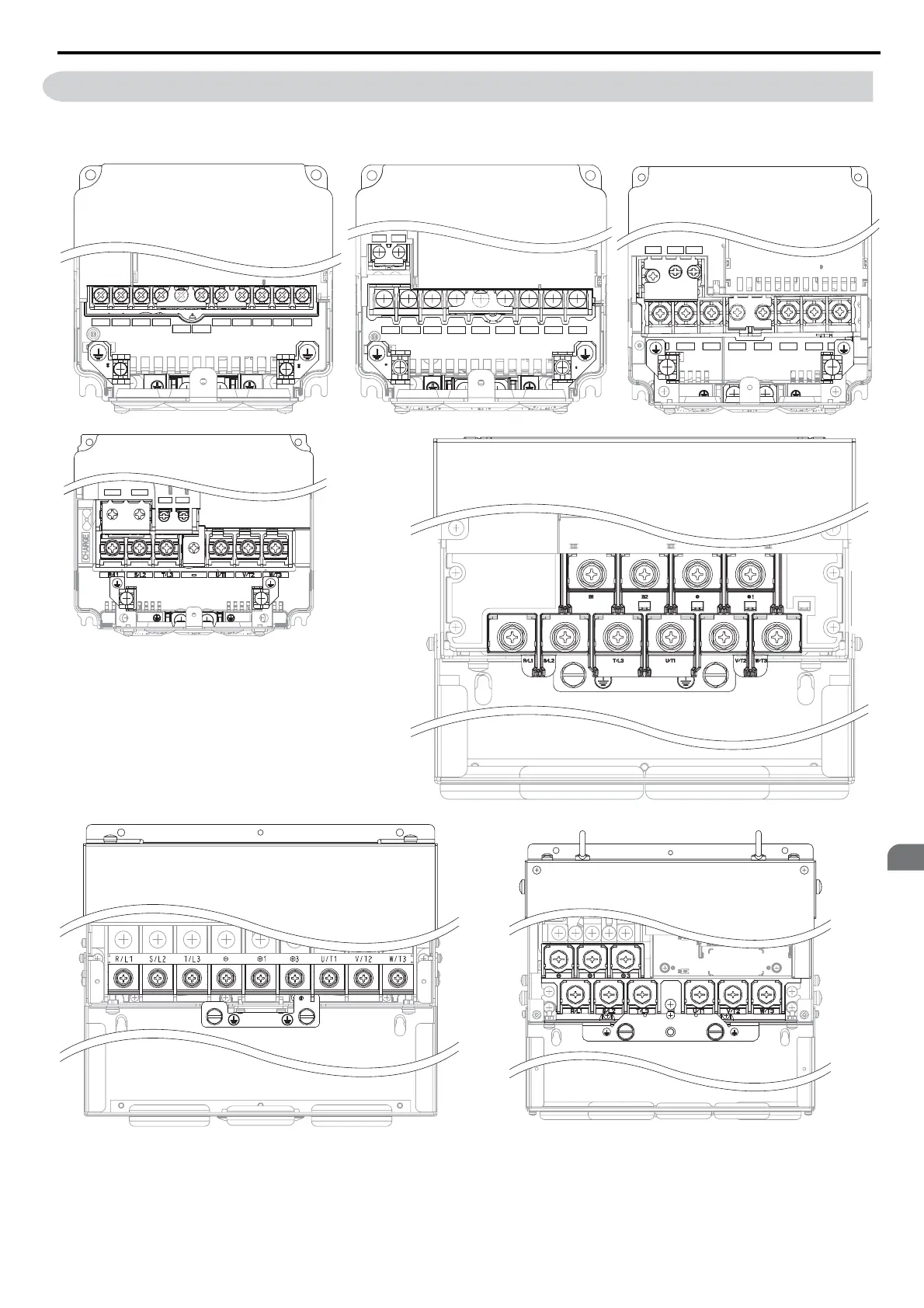
Figure 3.7 shows the different main circuit terminal arrangements for the drive capacities.
Figure 3.6
Figure 3.2 Main Circuit Terminal Block Configuration
<1> Terminal board design differs slightly for models CIMR-T2A0250 through 2A0415 and 4A0208 through 4A0362.
R/L1 S/L2 T/L3 B1 B2 U/T1 V/T2 W/T3
+1 +2
–
U/T1 V/T2 W/T3
+1 +2
R/L1 S/L2 T/L3
–
B1
B2
S/L2 T/L3 U/T1 V/T2 W
+1 +2
B1 B2
–
B1 B2
+1 +2
CIMR-T
2A0169, 0211, 0250, 0312, 0360, 0415
CIMR-T
4A0139, 0165, 0208, 0250, 0296, 0362
<1>
CIMR-T2A0004, 0006, 0010, 0012,
0021ޓ
CIMR-T4A0002, 0004, 0005, 0007,
0009, 0011
CIMR-T2A0030, 0040
CIMR-T4A0018, 0023
CIMR-T2A0056
CIMR-T4A0031, 0038, 0044
CIMR-T2A0069, 0081
CIMR-T2A0110, 0138
CIMR-T4A0058, 0072
CIMR-T4A0088, 0103
YEG