3.8 Control Circuit Wiring
64 YASKAWA ELECTRIC SIEP C710616 30B YASKAWA AC Drive T1000A Technical Manual
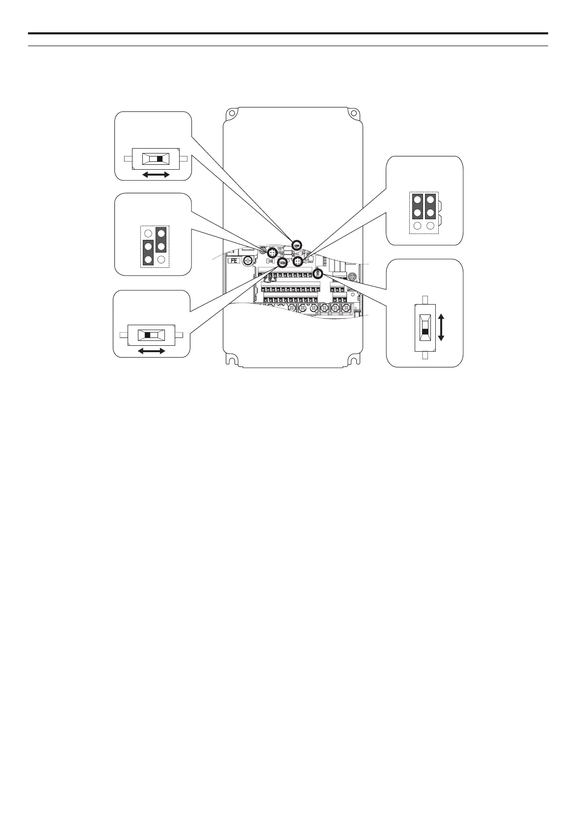
u Switches and Jumpers on the Terminal Board
The terminal board is equipped with several switches used to adapt the drive I/Os to the external control signals.
Figure 3.22 shows the location of these switches. Refer to Control I/O Connections on page 65 for setting instructions.
Figure 3.27
Figure 3.22 Locations of Jumpers and Switches on the Terminal Board
E(G)
HC H1 H2 DM+ DM- IG R+ R- S+ S-
S1 S2 S3 S4 S5 S6 S7 S8 SN SC SP
V+ AC V- A1 A2 A3 FM AM AC MP RP AC
VI
DIP Switch S1
Terminal A2 Signal
Selection
PTC
AI
DIP Switch S4
Terminal A3 Analog/
PTC Input Sel.
AM
FM
V
I
Jumper S5
Terminal AM/FM Signal
Selection
Jumper S3
Terminal H1/H2
Sink/Source Sel.
DIP Switch S2
RS-422/485 Termination
Resistor
Off On
YEG