5.7 H: Terminal Functions
190 YASKAWA ELECTRIC SIEP C710616 30B YASKAWA AC Drive T1000A Technical Manual
Setting 71: Speed/Torque Control switch
Switches the drive between Torque Control and Speed Control. Torque Control is enabled when the terminal is closed,
and Speed Control is enabled when the terminal is open. Note that parameter d5-01 must be set to 0 when using this
function. See d5: Torque Control on page 158 and Switching Between Torque and Speed Control on page 160.
Setting 72: Zero Servo
Used to activate the Zero Servo function that can be used to lock the rotor at a certain position. Refer to b9: Zero Servo
on page 139 for details.
Setting 77: ASR gain switch
Switches the ASR gain between the values set to C5-01 and C5-03. The gain set to C5-03 is enabled when the terminal is
closed, and C5-01 is enabled when the terminal opens again. See C5-01, C5-03 / C5-02, C5-04: ASR Proportional Gain
1, 2 / ASR Integral Time 1, 2 on page 148 for a more detailed description.
Setting 78: External torque reference polarity inversion
Reverses the direction of the torque reference when the terminal closes. Refer to d5: Torque Control on page 158 and
Setting the Torque Reference, Speed Limit, and Torque Compensation Values on page 158 for details.
Setting 7C, 7D: Short Circuit Braking (N.O., N.C.) (OLV/PM, AOLV/PM)
An input programmed for this function can be used to activate Short Circuit Braking in Open Loop Vector control modes
for PM motors. By linking all three phases of a PM motor, Short Circuit Braking creates a braking torque that can be used
to stop a rotating motor or prevent a motor from coasting due to external forces. Parameter b2-18 can be used to limit the
current during Short Circuit Braking.
Setting 7E: Forward/reverse detection (for V/f Control with Simple PG Feedback)
When a digital input is programmed for this function, the input determines the motor rotation direction for V/f Control
with Simple PG feedback (A1-02 = 0 and H6-01 = 3). If the input is open, the speed feedback signal is considered to be
forward. If the input is closed, it is considered to be in reverse. Refer to H6: Pulse Train Input/Output on page 208.
u H2: Multi-Function Digital Outputs
n H2-01 to H2-03: Terminal M1-M2, M3-M4, and M5-M6 Function Selection
The drive has three multi-function output terminals. Table 5.22 lists the functions available for theses terminals using
H2-01, H2-02, and H2-03.
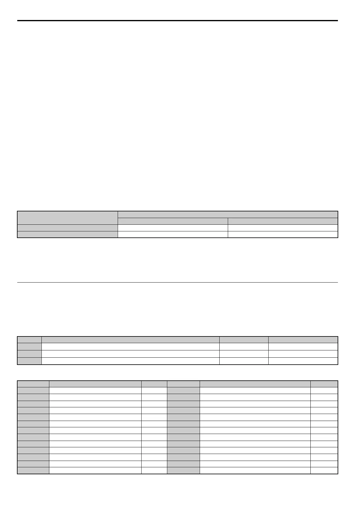
Table 5.22 Multi-Function Digital Output Terminal Settings
DIgital Input Function
Drive Operation
Input Open Input Closed
Setting 7C (N.O.) Normal operation Short Circuit Braking
Setting 7D (N.C.) Short-Circuit Braking Normal operation
No. Parameter Name Setting Range Default
H2-01
Terminal M1-M2 Function Selection
0 to 161 0: During run
H2-02
Terminal M3-M4 Function Selection
0 to 161 1: Zero Speed
H2-03
Terminal M5-M6 Function Selection
0 to 161 2: Speed agree 1
Setting Function Page Setting Function Page
0 During run 191 1C Motor 2 selection 197
1 Zero Speed 191 1D During regeneration 197
2 Speed agree 1 191 1E Restart enabled 197
3 User-set speed agree 1 192 1F Motor overload alarm (oL1) 197
4 Frequency detection 1 192 20 Drive overheat pre-alarm (oH) 197
5 Frequency detection 2 193 2F Maintenance period 197
6 Drive ready 193 30 During torque limit 198
7 DC bus undervoltage 193 31 During speed limit 198
8 During baseblock (N.O.) 193 32 During speed limit in Torque Control 198
9 Frequency reference source 194 33 Zero Servo complete 198
A Run command source 194 37 During frequency output 198
B Torque detection 1 (N.O.) 194 38 Drive enabled 198
C Frequency reference loss 194 39 Watt hour pulse output 198