5.7 H: Terminal Functions
YASKAWA ELECTRIC SIEP C710616 30B YASKAWA AC Drive T1000A Technical Manual 191
Parameter Details
5
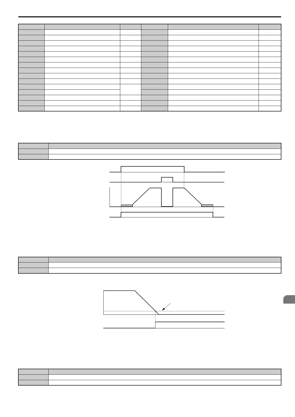
Setting 0: During Run
Output closes when the drive is outputting a voltage.
Figure 5.54
Figure 5.54 During Run Time Chart
Setting 1: Zero Speed
Terminal closes whenever the output frequency or motor speed (CLV, CLV/PM) falls below the minimum output
frequency set to E1-09 or b2-01.
Note: When using CLV or CLV/PM control modes, the zero speed level is defined by b2-01. In all other control modes, the zero speed
level is the minimum output frequency set to E1-09.
Figure 5.55
Figure 5.55 Zero-Speed Time Chart
Setting 2: Speed agree 1 (f
ref
/f
out
Agree 1)
Closes whenever the actual output frequency or motor speed (CLV, CLV/PM) is within the Speed Agree Width (L4-02)
of the current frequency reference regardless of the direction.
D Braking resistor fault 194 3C LOCAL/REMOTE Status 198
EFault 194 3D During Speed Search 198
F Through mode 194 3E PID feedback low 199
10 Minor fault 194 3F PID feedback high 199
11 Fault reset command active 194 4A During KEB operation 199
12 Timer output 194 4B During Short Circuit Braking 199
13 Speed agree 2 195 4C During Fast Stop 199
14 User-set speed agree 2 195 4E <1> Braking transistor fault (rr) 199
15 Frequency detection 3 196 4F <1> Braking resistor overheat (rH) 199
16 Frequency detection 4 196 50 Disturb Function Up 199
17 Torque detection 1 (N.C.)
194
51 Disturb Function Enabled/Disabled 199
18 Torque detection 2 (N.O.) 52 Uv during KEB 199
19 Torque detection 2 (N.C.) 194 60 Internal cooling fan alarm 199
1A During reverse 197 61 Rotor Position Detection Completed 199
1B During baseblock (N.C.) 197 100 to 161 Functions 0 to 61 with inverse output 199
<1> This function is not available in models CIMR-T2A0169 to 2A0415 and 4A0088 to 4A0362.
Status Description
Open Drive is stopped.
Closed A Run command is input or the drive is during deceleration or during DC injection.
Status Description
Open Output frequency is above the minimum output frequency set to E1-09 or b2-01
Closed Output frequency is less than the minimum output frequency set to E1-09 or b2-01
Status Description
Open Output frequency or motor speed does not match the frequency reference while the drive is running.
Closed Output frequency or motor speed is within the range of frequency reference ±L4-02.
Setting Function Page Setting Function Page
ON
ON
OFF
OFF
ONOFF
Run command
Baseblock
command
Output
frequency
During Run
OFF
Output frequency
or
motor speed
Zero Speed
ON
E1-09 (Max. Output Frequency) or
b2-01 (Zero Speed Level)